

The papers and monographs below are of general interest. We also offer the following topical pages as well:
- Pile Driving in Practice
- Pile-Soil Interaction (including static methods of pile capacity analysis)
- Programs and spreadsheet for pile capacity analysis
Detailed information on pile dynamics and the wave equation is here.
Allowable Stresses for the Upside-Down Timber Industry
Ronald W. Wolfe, Research Engineer
USDA Forest Service
Prepared for publication in International Conference on Wood Poles and Piles
September 1989
Round timbers have been used as foundation piling in North America for over 250 years, yet only in the last 50 years have concerns been raised about the need for allowable stresses for such timbers. Several organizations have published standards that govern the selection and derivation of working stress values for timber piles. This paper discusses the background for the ASTM derivations and factors to consider for improving model estimates of timber pile design stresses.
Analysis of the Pile Load Test Program at the Lock and Dam 26 Replacement Project
Jean-Louis Briaud and Larry M. Tucker, Texas A&M University
U.S. Army Corps of Engineers
Miscellaneous Paper GL-88-11
June 1988
Prior to performing twenty-eight axial and two lateral load tests on piles at the Mississippi River Lock and Dam 26 project in Alton, IL, an in situ test program was conducted. The program consisted of four cone penetration tests, twelve pressuremeter test borings, and four standard penetration test borings. Comparisons of pile capacity predictions were made for each of the in situ test methods. The initial study generated four reports and voluminous test data.
Assessment of Axially-Loaded Pile Dynamic Design Methods and Review of INDOT Axially-Loaded Pile Design Procedure
Dimitrios Loukidis, Rodrigo Salgado, and Grace Abou-Jaoude
FHWA/IN/JTRP-2008/6
October 2008
The general aim of the present research is to identify areas of improvement and propose changes in the current methodologies followed by INDOT for design of axially loaded piles, with special focus on the dynamic analysis of pile driving. Interviews with INDOT geotechnical engineers and private geotechnical consultants frequently involved in INDOT’s deep foundation projects provided information on the methods and software currently employed. It was found that geotechnical engineers rely on static unit soil resistance equations that were developed over twenty years ago and that have a relatively large degree of empiricism. Updated and improved static design equations recently proposed in the literature have not yet been implemented in practice. Pile design relies predominantly on SPT data; cone penetration testing is performed only occasionally. Dynamic analysis of pile driving in standard practice is performed using Smith-type soil reaction models. A comprehensive review of existing soil reaction models for 1-dimensional dynamic pile analysis is presented. This review allowed an assessment of the validity of existing models and identification of their limitations. New shaft and base reaction models are developed that overcome shortcomings of existing models and that are consistent with the physics and mechanics of pile driving. The proposed shaft reaction model consists of a soil disk representing the near field soil surrounding the pile shaft, a plastic slider-viscous dashpot system representing the thin shear band forming at the soil-pile interface located at the inner boundary of the soil disk, and farfield-consistent boundaries placed at the outer boundary of the soil disk. The soil in the disk is assumed to follow a hyperbolic stress-strain law. The base reaction model consists of a nonlinear spring and a radiation dashpot connected in parallel. The nonlinear spring is formulated in a way that reproduces realistically the base load-settlement response under static conditions. The initial spring stiffness and the radiation dashpot take into account the effect of the high base embedment. Both shaft and base reaction models capture effectively soil nonlinearity, hysteretic damping, viscous damping, and radiation damping. The input parameters of the models consist of standard geotechnical parameters, thus reducing the level of empiricism in calculations to a minimum. Data collected during the driving of full-scale piles in the field and model piles in the laboratory are used for validating the proposed models.
Assessment of the Feasibility of the Application of Threaded Connections in Offshore Platform Caissons
M. Q. Smith, T. S. Rennick, C. J. Waldhart and C. D. Redding, Southwest Research Institute
Minerals Management Service
SwRI Project No. 06-8955
September 1998
This document summarizes the findings for phase one of a two-phase study assessing the feasibility of applying threaded connections in offshore platform caissons. Please note that the report is not structured in accordance with the work task breakdown defined in the program scope of work. Rather, existing caisson and threaded connection design practices are addressed independently of each other in two separate sections, while a third section integrates these into a discussion of their application to threaded connection designs for caisson structures. Following this discussion, recommendations are made for development of a general guideline, and an accompanying scope of work is outlined for the second phase of the feasibility study.
Behavior of Fiber-Reinforced Polymer (FRP) Composite Piles Under Vertical Loads
FHWA-HRT-04-107
August 2006
Composite piles have been used primarily for fender piles, waterfront barriers, and bearing piles for light structures. In 1998, the Empire State Development Corporation (ESDC) undertook a waterfront rehabilitation project known as Hudson River Park. The project is expected to involve replacing up to 100,000 bearing piles for lightweight structures. The corrosion of steel, deterioration of concrete, and vulnerability of timber piles has led ESDC to consider composite materials, such as fiber-reinforced polymers (FRP), as a replacement for piling made of timber, concrete, or steel. Concurrently, the Federal Highway Administration (FHWA) initiated a research project on the use of FRP composite piles as vertical load-bearing piles.
A full-scale experiment, including dynamic and static load tests (SLT) on FRP piles was conducted at a site provided by the Port Authority of New York and New Jersey (PANY&NJ) at its Port of Elizabeth facility in New Jersey, with the cooperation and support of its engineering department and the New York State Department of Transportation (NYSDOT). The engineering use of FRP-bearing piles required field performance assessment and development and evaluation of reliable testing procedures and design methods to assess short-term composite material properties, load-settlement response and axial-bearing capacity, drivability and constructability of composite piling, soil-pile interaction and load transfer along the installed piling, and creep behaviour of FRP composite piles under vertical loads. This project includes:
- Development and experimental evaluation of an engineering analysis approach to establish the equivalent mechanical properties of the composite material. The properties include elastic modulus for the initial loading quasilinear phase, axial compression strength, inertia moment, and critical buckling load. The composite material used in this study consisted of recycled plastic reinforced by fibreglass rebar (SEAPILETM composite marine piles), recycled plastic reinforced by steel bars, and recycled plastic reinforced with randomly distributed fibreglass (Trimax), manufactured respectively by Seaward International Inc., Plastic Piling, Inc., and U.S. Plastic Lumber.
- Static load tests on instrumented FRP piles. The instrumentation schemes were specifically designed for strain measurements. The experimental results were compared with current design codes as well as with the methods commonly used for evaluating the ultimate capacity, end bearing capacity, and shaft frictional resistance along the piles. As a result, preliminary recommendations for the design of FRP piles are proposed.
- Analysis of Pile Driving Analyser® (PDA) and Pile Integrity Tester (PIT) test results using the Case Pile Wave Analysis Program (CAPWAP) and the GRL Wave Equation Analysis of Piles program GRLWEAP to establish the dynamic properties of the FRP piles. The PDA also was used to evaluate the feasibility of installing FRP piles using standard pile driving equipment. Pile bearing capacities were assessed using the CAPWAP program with the dynamic data measured by the PDA, and the calculated pile capacities were compared to the results of static load tests performed on the four FRP piles.
The dynamic and static loading test on instrumented FRP piles conducted in this project demonstrated that these piles can be used as an alternative engineering solution for deep foundations. The engineering analysis of the laboratory and field test results provided initial data basis for evaluating testing methods to establish the dynamic properties of FRP piles and evaluating their integrity and drivability. Design criteria for allowable compression and tension stresses in the FRP piles were developed considering the equation of the axial force equilibrium for the composite material and assuming no delamination between its basic components. However, the widespread engineering use of FRP piles will require further site testing and full-scale experiment to establish a relevant performance database for the development and evaluation of reliable testing procedure and design methods.
Check List for Design of Pile Foundations
Ralph B. Peck
The design of a pile foundation cannot be carried out by cookbook procedures. Nevertheless, the design can proceed in a rational matter such that no important points are overlooked. This checklist is undoubtedly oversimplified, but it may prove useful.
Deep Foundations–Specifications
Gay D. Jones, Jr., Howard, Needles, Tammer and Bergendoff
An overview of specifications for deep foundations, from various sources.
Design and Performance Verification of UHPC Piles for Deep Foundations (Final report of project entitled Use of Ultra-High Performance Concrete in Geotechnical and Substructure Applications)
T. Vande Voort, M. Suleiman, and S. Sritharan, Iowa State University
IHRB Project TR-558
November 2008
The strategic plan for bridge engineering issued by AASHTO in 2005 identified extending the service life and optimizing structural systems of bridges in the United States as two grand challenges in bridge engineering, with the objective of producing safer bridges that have a minimum service life of 75 years and reduced maintenance cost. Material deterioration was identified as one of the primary challenges to achieving the objective of extended life. In substructural applications (e.g., deep foundations), construction materials such as timber, steel, and concrete are subjected to deterioration due to environmental impacts. Using innovative and new materials for foundation applications makes the AASHTO objective of 75 years service life achievable. Ultra High Performance Concrete (UHPC) with compressive strength of 180 MPa (26,000 psi) and excellent durability has been used in superstructure applications but not in geotechnical and foundation applications. This study explores the use of precast, prestressed UHPC piles in future foundations of bridges and other structures. An H-shaped UHPC section, which is 10-in. (250-mm) deep with weight similar to that of an HP10×57 steel pile, was designed to improve constructability and reduce cost. In this project, instrumented UHPC piles were cast and laboratory and field tests were conducted. Laboratory tests were used to verify the moment-curvature response of UHPC pile section. In the field, two UHPC piles have been successfully driven in glacial till clay soil and load tested under vertical and lateral loads. This report provides a complete set of results for the field investigation conducted on UHPC H-shaped piles. Test results, durability, drivability, and other material advantages over normal concrete and steel indicate that UHPC piles are a viable alternative to achieve the goals of AASHTO strategic plan.
Dynamic Behavior of Pile Groups
Arnir M. Kaynia and Eduardo Kausel, Massachusetts Institute of Technology
The objective of this paper is to present solutions to determine the dynamic behaviour of pile groups using finite element methods.


To order copies, click on the volume you’re looking for:
- Design and Construction of Driven Pile Foundations Volume I
- Design and Construction of Driven Pile Foundations Volume II
- Design and Construction of Driven Pile Foundations; Comprehensive Design Examples
Design and Construction of Driven Pile Foundations
Federal Highway Administration
FHWA-NHI-16-009, FHWA-NHI-16-010 and FHWA-NHI-16-064 (NHI Courses 132021 and 132022)
September 2016
The purpose of this manual is to provide updated, state-of-the-practice information for the design and construction of driven pile foundations in accordance with the Load and Resistance Factor Design (LRFD) platform. Engineers and contractors have been designing and installing pile foundations for many years. During the past three decades, the industry has experienced several major improvements including newer and more accurate methods of predicting and measuring geotechnical resistance, vast improvements in design software, highly specialized and sophisticated equipment for pile driving, and improved methods of construction control. Previous editions of the FHWA Design and Construction of Driven Pile Foundations manual were published 1985, 1996, and 2006 and chronicle the many changes in design and construction practice over the past 30 years. This two volume edition, GEC-12, serves as the FHWA reference document for highway projects involving driven pile foundations.
Volume I, FHWA-NHI-16-009, covers the foundation selection process, site characterization, geotechnical design parameters and reporting, selection of pile type, geotechnical aspects of limit state design, and structural aspects of limits state design. Volume II, FHWA-NHI-16-010, addresses static load tests, dynamic testing and signal matching, rapid load testing, wave equation analysis, dynamic formulas, contract documents, pile driving equipment, pile accessories, driving criteria, and construction monitoring. Comprehensive design examples are presented in publication FHWA-NHI-16-064.
Throughout this manual, numerous references will be made to the names of software or technology that are proprietary to a specific manufacturer or vendor. Please note that the FHWA does not endorse or approve commercially available products, and is very sensitive to the perceptions of endorsement or preferred approval of commercially available products used in transportation applications. Our goal with this development is to provide recommended technical guidance for the safe design and construction of driven pile foundations that reflects the current state of practice and provides information on advances and innovations in the industry. To accomplish this, it is necessary to illustrate methods and procedures for design and construction of driven pile foundations. Where proprietary products are described in text or figures, it is only for this purpose.
The primary audience for this document is: agency and consulting engineers specialized in geotechnical and structural design of highway structures; engineering geologists and consulting engineers providing technical reviews, or who are engaged in the design, procurement, and construction of driven pile foundations This document is also intended for management, specification and contracting specialists, as well as for construction engineers interested in design and contracting aspects of driven pile systems.
We also have the two previous versions of this document:
- FHWA-NHI-05-042 and FHWA-NHI-05-043, NHI Courses No. 132021 and 132022.
- FHWA NHI-97-013. This FHWA monograph has information on every driven pile related program we offer except for Microwave and LLP97. They include WEAP87, COM624P, SPILE and DRIVEN.
- For quick reference, we also have the FHWA’s Pile Driving Guildelines
Design and Construction of Driven Pile Foundations — Lessons Learned on the Central Artery/Tunnel Project
FHWA-HRT-05-159
June 2006
Five contracts from the Central Artery/Tunnel (CA/T) project in Boston, MA, were reviewed to document issues related to design and construction of driven pile foundations. Given the soft and compressible marine clays in the Boston area, driven pile foundations were selected to support specific structures, including retaining walls, abutments, roadway slabs, transition structures, and ramps. This report presents the results of a study to assess the lessons learned from pile driving on the CA/T. This study focused on an evaluation of static and dynamic load test data and a case study of significant movement of an adjacent building during pile driving. The load test results showed that the piles have more capacity than what they were designed for. At the site of significant movement of an adjacent building, installation of wick drains and preaugering to mitigate additional movement proved to be ineffective. Detailed settlement, inclinometer, and piezometer data are presented.
Design Criteria for Driven Piles in Permafrost
Dennis Nottingham and Alan B. Christopherson
Peratrovich, Nottingham & Drage, Inc.
January 1983
Past placement of structural foundation support piles in frozen soils generally has been performed using drilled and slurry backfill techniques. The early success of specially modified H-pile structural shapes driven into permafrost, and the promise of more economical and faster methods of pipe pile placement, has fostered development of refined pile driving techniques on the North Slope of Alaska. The proposed criteria presented in this paper are primarily addressed to the practicing design engineer, including design and construction considerations for driven piles in permafrost. A s more research and experience accumulate, factors in this report may change. The reader is cautioned to use the findings in this paper with discretion, and only after thorough confirmation of actual site conditions.
Design of Deep Foundations
D. Michael Holloway
Deep Foundations Institute, Annual Meeting, 8-9 October 1980, La Jolla, CA
An outline overview of the essential elements of the successful design of deep foundations. The meeting venue where this was presented had its liquor license suspended during the conference, so this is probably the most sober document available on the subject.
Design of Pile Foundations
EM 1110-2-2906
15 January 1991
This manual provides information, foundation exploration and testing procedures, load test methods, analysis techniques, allowable criteria, design procedures, and construction consideration for the selection, design, and installation of pile foundations. The guidance is based on the present state of the technology for pile-soil-structure-foundation interaction behavior. This manual provides design guidance intended specifically for the geotechnical and structural engineer but also provides essential information for others interested in pile foundations such as the construction engineer in understanding construction techniques related to pile behavior during installation. Since the understanding of the physical causes of pile foundation behavior is actively expanding by better definition through ongoing research, prototype, model pile, and pile group testing and development of more refined analytical models, this manual is intended to provide examples and procedures of what has been proven successful. This is not the last nor final word on the state of the art for this technology. We expect, as further practical design and installation procedures are developed from the expansion of this technology, that these updates will be issued as changes to this manual.
Effect of Pile-Driving Induced Vibrations on Nearby Structures and Other Assets
Adda Athanasopoulos-Zekkos, Richard D. Woods and Athena Grizi
University of Michigan
RC-1600, ORBP Number OR10-046
November 2013
The work described here represents an attempt to understand the mechanisms of energy transfer from steel H-piles driven with diesel hammers to the surrounding soil and the energy attenuation through the soil by measuring ground motion vibrations in the near vicinity of the pile. Attenuation rates of vibration decay with radial distance from the driven pile were calculated. A spreadsheet tool was developed to estimate distances from the pile at which the threshold settlement vibrations may be exceeded.
Efficiency and Energy Transfer in Pile Driving Systems
A description of the basic principles of energy transfer and efficiency ratings as they apply to pile driving equipment and the piles they drive.
Experimental Evaluation and Design of Unfilled and Concrete- Filled FRP Composite Piles
Task 3 – FRP Composite Pile Flexural Testing
Dale Lawrence, Roberto Lopez-Anido, Thomas Sandford, Keenan Goslin and Xenia Rofes
University of Maine
AEWC Report Number 15-2-1199, ME 15-08
June 2014
The overall goal of this project is the experimental evaluation and design of unfilled and concrete-filled FRP composite piles for load-bearing in bridges. This report covers Task 3, FRP Composite Pile Flexural Testing. Hollow and concrete filled fiber reinforced polymer (FRP) piles were tested in four point bending to examine degradation in stiffness, ultimate strength, and loss of concrete‐FRP composite action due to pile driving and cyclic loading. Testing showed a high level of variability in the ultimate strength of the piles, but all driven and load-cycled samples broke within the upper and lower bounds of the control piles. This series of tests showed no degradation in stiffness during static tests in the piles due to driving or cyclic loading. However, driving and cyclic loading appear to affect composite action between the FRP shell and concrete.
Implementación de una Solución Analítica para el Fenómeno de Propagación Unidimensional de Ondas en Pilotes y su Adaptación para la Interpretación de Resultados de la Prueba de Integridad de Pilotes (PIT)
(Implementation of an Analytic Solution for the Phenomenon of One-Dimensional Propagation of Waves in Piles and its Adaptation for Result Interpretation of Pile Integrity Test (PIT))
Víctor Hugo Restrepo Botero
Pontifica Universidad Javeriana, Bogotá
We feature this paper because it references extensively our own Closed Form Solution of the Wave Equation for Piles, and because it takes the solution a step further with the use of Fast Fourier Transforms. In Spanish. We have this in two versions:
In Situ Geophysical Investigation of the Pile Test Section, Sardis Dam, Mississippi
José L. Liopis
Geotechnical Laboratory
U.S. Army Corps of Engineers
Waterways Experiment Station
Technical Report GL-94-1
January 1994
The U.S. Amy Engineer District, Vicksburg (LMK) has undertaken several studies to evaluate the probable behavior of Sardis Dam, Sardis, MS during
and after an earthquake. The studies were conducted because of concerns about the stability of the dam under seismic conditions and the possibility of liquifaction of portions of the dam and its foundation. Results of the investigation have concluded that some modifications should be made to the dam to improve its stability. relative to seismic loading. One remedial measure that is being considered to increase soil stability is to drive prestressed concrete piles through weak layers of the dam and into stronger layers below. The piles are designed to restrain large flow deformations and have the additional benefit of densifying the surrounding soil. A pile test section was constructed on the downstream toe of the dam to evaluate this method of remediation.
As part of the ongoing LMK Sardis Dam remediation study and as a part of the Repair, Evaluation, Maintenance and Rehabilitation (REMR) work unit entitled “Assessment of Requirements for Seismic Stability Remediation” personnel of the US Army Waterways Experiment Station (WES) conducted a geophysical investigation at the pile test section at Sardis Dam. The objective of the geophysical investigation was to assess soil strength changes due to remediation efforts at the test section.
Investigation of the Resistance of Pile Caps to Lateral Loading
Robert L. Mokwa
Virginia Polytechnic Institute
September 1999
Bridges and buildings are often supported on deep foundations. These foundations consist of groups of piles coupled together by concrete pile caps. These pile caps, which are often massive and deeply buried, would be expected to provide significant resistance to lateral loads. However, practical procedures for computing the resistance of pile caps to lateral loads have not been developed, and, for this reason, cap resistance is usually ignored. Neglecting cap resistance results in estimates of pile group deflections and bending moments under load that may exceed the actual deflections and bending moments by 100 % or more.
Advances could be realized in the design of economical pile-supported foundations, and their behavior more accurately predicted, if the cap resistance can be accurately assessed. This research provides a means of assessing and quantifying many important aspects of pile group and pile cap behavior under lateral loads.
The program of work performed in this study includes developing a full-scale field test facility, conducting approximately 30 lateral load tests on pile groups and pile caps, performing laboratory geotechnical tests on natural soils obtained from the site and on imported back-fill materials, and performing analytical studies. A detailed literature review was also conducted to assess the current state of practice in the area of laterally loaded pile groups.
A method called the “group-equivalent pile” approach (abbreviated GEP) was developed for creating analytical models of pile groups and pile caps that are compatible with established approaches for analyzing single laterally loaded piles. A method for calculating pile cap resistance-deflection curves (p-y curves) was developed during this study, and has been programmed in the spreadsheet called PYCAP. A practical, rational, and systematic procedure was developed for assessing and quantifying the lateral resistance that pile caps provide to pile groups.
Comparisons between measured and calculated load-deflection responses indicate that the analytical approach developed in this study is conservative, reasonably accurate, and suitable for use in design. The results of this research are expected to improve the current state of knowledge and practice regarding pile group and pile cap behaviour.
Lateral Motion of Piles During Driving
T.J. Poskitt, Queen Mary College, University of London
Using an energy method, the lateral response of an initially curved raked pile to an axial blow from a piling hammer is derived. By treating the blow as an impulsive force, a considerable simplification results which enables a closed form solution to be obtained. The solution is in general terms and enables all boundary conditions of practical interest to be studied. The cases of cantilever and a propped cantilever pile are presented as being of most practical interest. Propping corresponds to supporting the hammer in leaders and results in lower bending stresses. The most critical case is the raked cantilever pile. This can experience significant bending stresses.
Loading Rate Effects on Pile Load-Displacement Behaviour Derived from Back-Analysis of Two Load Testing Procedures
We feature this thesis for several principal reasons.
First, it is unusual in that it deals with both soil dynamics and wave propagation in piles in the same place. These two subjects are obviously related but are not tied together as often as one would like.
Second, it is an extensive treatment on the subject of loading rate in pile load testing. The significance of loading rate in testing is important both for the proper interpretation of the results and in relating the determined load to actual loads on piles, all of which have some kind of load rate.
Third, the background section of the thesis deals with many of the same soil models that were used in our own thesis. The soil modelling described in that work was heavily influenced by the work of Alain Holeyman, who supervised Charue’s thesis. The thesis also cites our own paper on the development of the ZWAVE wave equation analysis program, which used soil models that were a departure from Smith.
Nicolas Charue
Catholic University of Louvain, Belgium
Soils, like several other materials, exhibit strong time-dependent behaviour which can be evidenced in terms of creep or strain-rate effects. The degree of this rheological behaviour varies with the type of soil, its structure, and with the stress history. This effect is exacerbated in pile load testing where the procedure duration tends to be shortened under increasing time pressures. The modelling needed to interpret the results therefore becomes more and more complex, including soil viscosity, wave radiation into the soil and other significant phenomena.
Within this framework, it would be interesting to study the influence of the loading rate on the load-displacement behaviour of the pile through the results of two testing procedures loading piles with variable duration (Static Loading Test (SLT) used as reference and Dynamic Load Test (DLT)). Based on these data issued from two national research programs organised by the Belgian Building Research Institute (BBRI), the objective of the research reported herein is to refine the rheological parameters characterizing the influence of the loading rate within the framework of a relevant pile/soil interaction model fed with dynamic measurements acquired during pile Dynamic Load Tests. The final goal is to predict and simulate the quasi-static pile load settlement curve.
After an overview of the loading rate effects in the literature through the experimental and modelling aspects, the dynamic data measured on field are analysed. It has been observed that some relationships exist between maximum quantities such as: energy transmitted to the pile, pile head velocity and force and the settlements (maximum and permanent) measured after a sequence of blows during a DLT event. These relationships are similar for the sandy and clayey sites and repeatable in time. It has been found that there are some critical quantities (correlated with the hammer drop height) from which a significant settlement of the pile is possible while the pile does not settle if these quantities are not exceeded.
The pile/soil interaction system is described by a non-linear mass/spring/dashpot system supposed to represent the pile and the soil, with constitutive relationships existing within and between them. These relationships account for the static and the dynamic or rheologic behaviour. A back-analysis process based on a matching procedure between measured and computed curves (force and velocity) allows one to describe the pile/soil interaction in terms of constitutive and rheologic parameters based on the dynamic measurements. After optimization of the matching procedure, the parameters obtained are used to simulate the “static” load-settlement curve. The matching procedure is based on an automatic multi dimensional parameter perturbation analysis. Since the parameters influence the system response with a relative weight, they are sorted in order to optimize all the parameters by successively retrieving the most influential ones and working on the remaining ones.
A Laboratory and Field Study of Composite Piles for Bridge Substructures
Note: a review and use of the results of this study can be found here.
Miguel A. Pando, Carl D. Ealy, George M. Filz, J.J. Lesko, and E.J. Hoppe
FHWA-HRT-04-043
March 2006
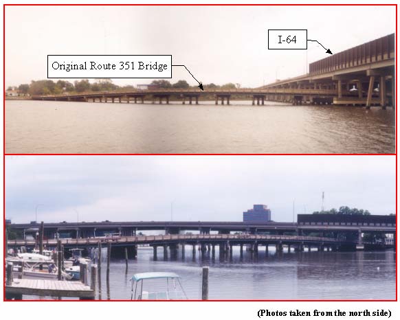
The most commonly used pile materials are steel, concrete, and wood. These materials can degrade, and the degradation rate can be relatively rapid in harsh marine environments. It has been estimated that the U.S. spends over $1 billion annually for repair and replacement of waterfront piling systems. This high cost has spurred interest in alternative composite pile materials such as fibre-reinforced polymers (FRPs), recycled plastics, and hybrid materials. Because only minimal performance data have been collected for composite piles, a research project was undertaken to investigate (1) soil-pile interface behaviour of composite piles, (2) the long-term durability of concrete-filled FRP shell composite piles, and (3) the driveability and axial and lateral load response of concrete-filled FRP composite piles and steel-reinforced recycled plastic piles by means of field tests and analyses. In addition, a long-term monitoring program was implemented at a bridge over the Hampton River in Virginia.
According to laboratory rest results, values of residual interface friction angle between three pile surfaces and a subrounded to rounded sand were 27, 25, and 28 degrees for a FRP composite pile, the recycled plastic pile, and the prestressed concrete pile respectively, while the values of residual interface friction angle between these piles and a subangular to angular sand were 29, 29, and 28 degrees for the FRP composite pile, the recycled plastic pile, and the prestressed concrete pile, respectively. Regarding durability of FRP composite piles, it was found that moisture absorption caused degradation of strength and stiffness of the FRP shells, but that freeze-thaw cycles had little effect. Analyses indicate that FRP degradation due to moisture absorption should have minimal impact on axial capacity of the FRP composite piles because most of the axial capacity is provided by the concrete infill; however, FRP degradation has a larger effect on lateral capacity because the FRP shell provides the capacity on the tension side of the pile. The field tests demonstrated that there were not major differences in driveability of the FRP composite pile, the recycled pile, and the prestressed concrete pile. In static load tests, the FRP composite pile and prestressed concrete pile exhibited similar axial and lateral stiffness, and the plastic pile was significantly less stiff. Conventional static analyses of axial load capacity, axial load versus settlement, and lateral load versus deflection provided reasonable predictions for the composite piles, at least to the levels of accuracy that can be achieved for more common pile materials. The long-term monitoring program has been implemented for an FRP composite pile and a prestressed concrete pile so that their load-transfer performance can be compared over time. The long-term monitoring is being done by Virginia DOT.
Mechanics of Diesel Pile Driving
Dave Rempe (1937-2010) was an eminent researcher and practicioner in the field of driven piles and the wave equation, having both worked in the field for Raymond, produced academic works such as this one, and consulted on numerous pile driving projects. You can see the tribute to his life here. In addition, he was a devoted family man and a great friend. His pastor noted that “Dave came to faith as an adult, and he studied diligently. His dog-eared Bible showed that he expended the same effort in his spiritual life that he did towards both work and family. I always appreciated his questions, as challenging as they might be.”
David Maher Rempe
University of Illinois
1975
Research was conducted into the mechanics of pile driving with diesel hammers. The first step consisted of an investigation of the mechanical and operational details of diesel pile hammers. Then, a mathematical simulation of diesel hammer operation was developed for purposes of wave equation analysis, which is an analytical method for prediction of pile load capacity and driving stress on the basis of driving resistance (pile penetration per hammer-blow). Finally, the performance characteristics of diesel pile hammers and the factors affecting performance were studied. The details of diesel hammer design and operation are described. Differences in design and operation among the various types of diesel hammer are discussed as they relate to pile-driving effectiveness. Design features related to inclined operation and soft-ground operation are discussed. The mathematical model of the diesel hammer is described in detail, with emphasis on the simulation of diesel combustion, steel-on-steel impact, and interaction of hammer operation with the dynamic response of pile and soil. In wave equation analysis of diesel pile driving, the mathematical hammer model is combined with models of the pile and soil to produce a total simulation of the hammer-pile-soil system.
Mechanics of Impact Pile Driving
Jerry F. Parola
University of Illinois
1970
Impact pile driving was studied by utilizing longitudinal wave propagation theory as an analytical tool . Field data from pile driving jobs was used to establish the validity and usefulness of the analytical techniques developed herein.
The theoretical treatment of the dynamics of impact pile driving included an analysis of both the force generated at the head of the pile and the response of the pile tip to a generated force pulse. A model consisting of a hammer system operating on the head of an infinitely long pile was used to determine both the pile force pulse and the transmitted energy. The model was used to make a dimensionless parameter study of the factors influencing force and energy. The driver system consisted of concentrated masses for both the ram and the drivehead and an energy absorbing spring (both linear and nonlinear) for the hammer cushion.
Soil and pile responses were investigated with respect to an arbitrary force pulse in order to assess the variables controlling pile penetration and load capacity. Special emphasis is placed on soil and pile response a t the pile tip; the soil model includes viscous damping, mass and an elastic-plastic spring.
Characteristics of the hammer-pile-soil system as a whole are summarized. Theoretical results using wave propagation theory are compared with both case histories and commonly used dynamic formulas. Correlation of wave analyses and field case histories are used to support the conclusion that wave propagation theory is the proper theoretical tool for pile driving analysis.
Modeling Embankment Induced Lateral Loads on Deep Foundations
(Slide Show Technical Presentation)
Dr. Siva Kesavan, URS Corporation
Professor Rajah Anandarajah, Johns Hopkins University
The problem analyzed in this presentation is inspired by a real-world problem where the construction of a landfill at a rate too fast caused damage to an adjacent bridge. Without presenting actual names, the problem is described and analyzed using an elasto-plastic finite element computer code (HOPDYNE) to illustrate how an advanced numerical procedure can help develop an understanding of the failure mechanism, and reveal the true cause of the failure in a complex problem like this, where loading and consolidation take place simultaneously. The problem involves soil-structure interaction. The geometry is too complex, raising questions concerning the validity of one-dimensional assumptions used in Terzaghi’s one-dimensional consolidation theory. The clayey soil in the foundation is too soft and is certain to behave highly plastically, raising questions about the validity of using elastic theories to calculate the stresses in the foundation caused by the weight of the landfill. In other words, the problem is too complex, pointing to the need for a method like the finite element method for not only verifying the validity of the conventional methods normally used in analyses, but also to explain the true cause of failure.
Static and dynamic analysis of an offshore mono-pile windmill foundation
L. Kellezi and P. B. Hansen
GEO – Danish Geotechnical Institute, Lyngby, Denmark
Different foundation concepts have been presented and applied to offshore windmill turbines designed and constructed all over the world. The advantages and disadvantages of different concepts are already outlined and research from universities and private companies continues with this respect. The choice of the foundation concept for an offshore windmill turbine is governed by several factors, which include soil conditions, the water depth at the location, the scour and erosion, the capacity of the turbines, the foundation cost etc. It is investigated that for offshore windmill turbines the foundation costs are approximately 25% of the total cost [1].
There are basically three types of foundations applied to different windmill parks. These are: gravity based, skirted and piled foundations. Piled foundations are the most common foundations for offshore structures. Driving the piles into the seabed is the standard method of installation [2]. Considering the soil conditions and other factors the mono-pile foundation concept was chosen for the windmill park at Horns Rev, Denmark. Such concept is also applied at Utgrunden and Bockstigen in Sweden and other places.
Large diameter mono-piles are generally used for offshore windmill turbines placed at shallow water. A lot of progress has been made in the last decades towards the development of engineering methods for the static and dynamic analysis of the pile foundations. Different approaches can be adopted in solving the problem. The p-y approach or Winkler model, [3-5] has been widely used to design piles subjected to lateral static or dynamic loading. Based on this approach the lateral soil-structure interaction can be modelled using empirically derived nonlinear springs and dashpots.
More rigorous finite element methods (FEM), which allow application of soil constitutive modeling and soil-pile nonlinear interaction, have been developed lately. Some representative FEM applications regarding pile foundation design are given by [6-9] where a series of 3D FEM studies were conducted on the behaviour of piles under static loads. For dynamic loads the problem can be considered as viscous-dynamic with material damping included, [10-11], or nonlinear-dynamic depending on the current situation.
A structure resting on pile foundations and subjected to dynamic vibrations with small amplitudes can be analyzed as a viscous-dynamic problem. However piles under earthquake excitations or pile driving analysis, which is associated with large amplitudes of vibrations and penetration, should be considered as a strongly nonlinear-dynamic problem, [12-13]. The mono-pile windmill foundation at Horns Rev is analyzed here for maximum static and dynamic loads. 3D nonlinear FEM design is carried out for static loads employing ABAQUS program. 3D axisymmetric viscous-dynamic analysis is carried out for dynamic loads as small vibration amplitudes are expected for a windmill turbine foundation structure. Self developed FEM programs are used in this case.
Static Testing of Deep Foundations
(pdf format)
Federal Highway Administration
FHWA-SA-91-042
February 1992
A majority of the bridges in the United States are supported on deep foundations. The economical design and construction of a pile foundation depends on the use of rational procedures to determine pile load capacity. Additional, unwarranted costs can result from either inadequate or overly conservative design and from construction claims related to pile driving difficulties.
A static load test is conducted to measure the response of a pile under applied load. Conventional static load test types include axial compressive, axial tensile and lateral load testing. The cost and engineering time associated with a load testing program should be justified by a thorough engineering analysis and foundation investigation. An adequate pile foundation design requires detailed subsurface exploration, appropriate soil testing, subsurface profile development, static pile analyses and selection of optimum pile type(s).
Static load tests provide the best means of determining pile capacity and, if properly designed, implemented and evaluated, should pay for themselves on most projects. Depending on availability of time and on cost considerations, the load testing program may be included either in the design or in the construction phase. Dynamic load tests, performed in conjunction with static load tests, greatly increase the cost-effectiveness of a pile load test program and should be specified whenever piles installed by impact driving are load-tested.
Many different procedures have been proposed for conducting pile load tests. The main differences are in the selection of loading systems, instrumentation requirements, magnitude and duration of load increments, and interpretation of results.
The objective of this manual is to present a comprehensive, easy-to-follow guide describing the steps required in planning, conducting and interpreting the results of static load tests on driven piles and drilled shafts. It is intended to serve as a reference for experienced engineers and as a learning aid for those not experienced in pile load testing. Types of testing covered include axial compressive, axial tensile and lateral load tests. A brief description of dynamic pile load testing is included in the Appendix.
Strength Evaluation of Round Timber Piles
Thomas Lee Wilkinson
U.S.D.A. Forest Service Research Paper FPL 101
December 1968
Foundation piles are used to support structures resting on soils having insufficient bearing strength to support footings for any but the lightest loads. Current practice is to design wood piles for loads of 15 to 25 tons when load tests are not conducted and for loads of 40 to 50 tons are justified by the load test. These higher loads produce stresses that approach the allowable stresses for green sawn timbers. Data are needed to verify that the higher design stresses are justified for timber piles. This study was conducted in two parts. In Part 1, strength properties in compression parallel to the grain and in bending were determined for 15 timber piles of each of 3 species– Douglas-fir, southern pine, and red oak. The results of these evaluations indicated the following average tip end crushing strengths: read oak 3,460 p.s.i., Douglas-fir 2,960 p.s.i., and southern pine 1,820 p.s.i. The three species ranked in the same order for modulus of rupture. In Part 2, the effect of kiln-drying of southern pine piles on crushing strength was investigated. Kiln- dried piles had about 12 percent less crushing strength than green piles when both were evaluated at the same moisture content. The strength values obtained in this study given an indication of the loads for which timber piles may be designed. The results should be useful in the development of timber pile specifications.
Theoretical Manual for Pile Foundations
Reed L. Mosher and William P. Dawkins
U.S. Army Corps of Engineers Information Technology Laboratory
ERDC/ITL TR-00-5
The purpose of this manual is to provide a detailed discussion of techniques used for the design/analysis of pile foundations. Several of the procedures have been implemented. Theoretical development of these engineering procedures and discussions of the limitations of each method are presented.
The purpose of a pile foundation is to transmit the loads of a superstructure to the underlying soil while preventing excessive structural deformations. The capacity of the pile foundation is dependent on the material and geometry of each individual pile, the pile spacing (pile group effect), the strength and type of the surrounding soil, the method of pile installation, and the direction of applied loading (axial tension or compression, lateral shear and moment, or combinations). Except in unusual conditions, the effects of axial and lateral loads may be treated independently.


One thought on “Papers and Documents on Pile Driving and Driven Piles”