
The Action of Soft Clay Along Friction Piles: Bay Mud Revisited
Lymon C. Reese
1983
Research at Berkeley more than three decades ago gave new insight into the behaviour of axially-loaded piles in clay. Numerous experiments and analytical studies performed since, many of which have been supported by the oil industry with respect to offshore platforms, have added significantly to a better understanding of the problem. Yet, the prediction of the “real” behaviour of such piles with effective-stress methods remains far beyond the present capabilities of geotechnical engineers.
A brief discussion is presented to elucidate the factors involved in the interaction between a pile and the clay with a view of establishing fundamental concepts. Models are described that serve as guidance to further research. Some results of studies at Berkeley and elsewhere are presented that are relevant to an improved understanding.
The thrust of the paper is to lay out the kinds of experiments that must be performed if the problem of an axially-loaded pile in clay is to be solved rationally. Further development of methods to predict the load versus settlement of a pile in soft clay must await the collection of a body of reliable data from field measurements. The discussion that is presented is built around the behaviour of a single pile for simplicity but the concepts presented apply to a group of closely-spaced piles. Also, for simplicity only the load transfer in side resistance is considered. End bearing is important, of course, but for a pile in soft clay the load carried in end bearing is frequently a small fraction of the load carried in side resistance.
Applications for New Research for Pile Supported Machine Foundations
W.E. Saul and T.W. Wolf
The use of piling for machine foundations can add flexibility for the designer, help solve special problems, and possibly reduce costs . A very complete method of analysis is presented with great flexibility in options available as well as a catalogue of very accurate pile models. A design for a power plant using the method is related as an example.
Axial Capacity of Driven Piles in Deltaic Soils Using the Cone Penetrometer Test
M.P. Davies, ConeTec Investigations Ltd.
P.K. Robertson and R.G. Campanella, University of British Columbia
A. Sy, Klohn Leonoff Ltd.
First International Symposium on Penetration Testing
March 1988
The prediction of axial pile capacity is a complex engineering problem. Traditional methods of data collection and subsequent analyses are frequently in error when compared to full-scale load tests. Cone penetration testing (CPT) provides a means by which continuous representative field data may be obtained. This paper compares the predictions from thirteen axial pile capacity methods with the results obtained from eight full-scale pile load tests on six different piles. The piles were steel pipe piles driven into deltaic soil deposits. The thirteen prediction methods, separated into direct and indirect classes, used data obtained from the CPT as input for analyses. A brief evaluation of each method investigated is presented and the preferred methods of analyses are identified.
Axial Capacity of Piles Supported on Intermediate Geomaterials
Robert Mokwa and Heather Brooks
FHWA/MT-08008/8117-32
September 2008
The natural variability of intermediate geomaterials (IGM’s) exacerbates uncertainties in deep foundation design and may ultimately increase construction costs. This study was undertaken to investigate the suitability of conventional pile capacity formulations to predict the axial capacity of piles driven into IGM formations. Data from nine Montana Department of Transportation bridge projects were collected, compiled and analysed. Axial pile analyses were conducted using a variety of existing method and computer programs, including: DRIVEN, GRLWEAP, FHWA Gates driving formula, WSDOT Gates driving formula, and an empirical method used by the Colorado Department of Transportation. The results of the analyses were compared to pile capacities conducted using the CAPWAP program.
The capacity comparisons clearly demonstrated the inherent variability of pile resistance in IGM’s. Most of the projects exhibited considerable variation between predicted capacities calculated using DRIVEN and measured CAPWAP capacities. For example, five of the six restrike analysis were overpredicted using DRIVEN, one by as much as 580%! The majority of shaft capacity predictions for cohesionless IGM’s were less than the measured CAPWAP capacities; the worst case was a 400% under prediction (a factor of 5.) Toe capacity predictions were also quite variable and random, with no discernable trends. This study indicates that the traditional semiempirical methods developed for soil by yield unreliable predictions for piles driven in to IGM deposits. The computed results may have little to no correlation with CAPWAP capacities measured during pile installation. Currently, CAPWAP capacity determinations during pile driving or static load tests represent the only reliable method for determining the capacity of piles driven into IGM formations.
The Bearing Capacity Of Rigid Piles Under Inclined Loads In Sand. II: Batter Piles
G.G. Meyerhof and G. Ranjan
Following the previous investigation reported in the first part on vertical piles, this second part of the paper presents an analysis of the results of loading tests on rigid batter piles under inclined load in sand. The bearing capacity of axially loaded batter piles is discussed by comparing experimental results and theoretical estimates. The theory for ultimate resistance of rigid vertical piles under horizontal loads is extended to that of laterally loaded batter piles. Model test results are compared with those of theoretical estimates and good agreement is found. Methods of analysis of vertical piles under inclined loads are extended to those of rigid batter piles under inclined loads in sand and the analysis is compared with some test results.
Behaviour of Axially Loaded Piles
Cheung Ka-Ching
University of Canterbury
1988
This project may be described in three parts. The first part mainly involves the evaluation of existing soil models under undrained conditions. The second part of the project is to evaluate the currently used methods for representation of the pile installation process. The third part of the work involves the study of the axially loaded pile problem, and particular interest is paid to the investigation of pile load displacement, shear transfer and load diffusion along the pile. Three different soil model have been used to represent the soil for this problem. Theoretical solutions have been compared with field test results.
The modified Cam-clay model and the more advanced bounding surface model developed from classical plasticity theories, and the rate-type model founded upon hypoelasticity theory have been studied. Model predictions of these three models were compared and evaluated base on results of triaxial tests and direct simple shear tests under undrained conditions. Both the modified Cam-clay model and the rate-type model are closely related by the similarity of their yield surfaces, but the rate type model requires only three soil parameters and provided reasonable agreement with test results on normally to heavily overconsolidated clay. The modified Cam-clay model is relatively restricted to the lightly overconsolidated clay. The sophisticated bounding surface model provides remarkable model prediction power to fit the test results, but numerous model parameters are required.
The cylindrical cavity expansion approach and the simple pile method, both of which may be used to simulate the pile installation process have been investigated. The rate-type model has been choosen to represent the soil. The simple pile method attempts to include the tip effect due to pile advancement which has been ignored in the cylindrical cavity expansion approach. The simple pile method approximates the strain field around the pile by an ideal fluid, but it is found that this method results in unrealistic pile-soil interaction. The predicted excess pore pressures from both methods were compared with field test results. This indicated that the simple pile method provided better agreement with test results than did the cylindrical cavity expansion approach.
An idealized one-dimensional pile model has been proposed. The modified Cam-clay model, bounding surface model and the rate-type model have all been used to simulated the soil response due to axial pile loading. Theoretical solutions were compared with three well documented pile test results. The pile tests were carried out in lightly to heavily overconsolidated clay deposits. The pile model predicted good agreement with test results, especially in regard to the pile load displacement response, shear transfer and load diffusion along the pile at low stress level.
Centrifugal Modeling of the Dynamic Response of Piles
J.H. Prevost and A.M. Abdel-Ghaffar
The dynamic response to laterally loaded single piles and pile groups (each consisting of four evenly-spaced piles, and spaced at different distances in each group) embedded in loose, dense, dry and saturated sands, is studied using centrifugal modeling techniques. The response of single piles and pile groups to forced vibrations was found to depend strongly on the magnitude and frequency of loading as well as the density of the soils. The results indicate that, as the level of force increased, 1) nonlinear softening behaviour was evidenced by a decrease in the resonant frequency of the soil-pile system, 2) there was an increase in internal soil-pile damping, and 3) the maximum bending moment moved progressively deeper below the soil surface and increased substantially in magnitude. Also, significant interaction effects were observed with close pile spacing. Finally, the experimental stiffness and damping results were compared with theoretical values as predicted by Novak’s work.
Comparative Modeling of Vertical Pile Groups
M.W. O’Neill and HoBoo Ha
The recent development of mathematical models for synthesizing load deformation behaviour of pile groups suggests the need for calibrating such models to field behaviour. Two generic models described herein are used t o model vertical load-deformation characteristics of five full – scale compression tests of pile groups in a variety of clay soils. Values of input parameters necessary to achieve reasonable compatibility with measurements are different in the two models. Those differences are explainable in terms of model mechanics. An extension of compression behaviour to load-uplift behaviour is described.
Comparison of Five Different Methods for Determining Pile Bearing Capacities
Wisconsin DOT 0092-07-04
August 2008
The purpose of this study is to assess the accuracy and precision with which five methods can predict axial pile capacity. The methods are the Engineering News formula currently used by Wisconsin DOT, the FHWA-Gates formula, the Pile Driving Analyzer, the Washington State DOT. Further analysis was conducted on the FHWA-Gates method to improve its ability to predict axial capacity. Improvements were made by restricting the application of the formula to piles with axial capacity less than 750 kips, and to apply adjustment factors based on the pile being driven, the hammer being used, and the soil into which the pile is being driven. Two databases of pile driving information and static or dynamic load tests were used evaluate these methods. Analysis is conducted to compare the impact of changing to a more accurate predictive method, and incorporating LRFD. The results of this study indicate that a “corrected” FHWA-Gates and the WSDOT formulas provide the greatest precision. Using either of these two methods and changing to LRFD should increase the need for foundation (geotechnical) capacity by less than 10 percent.
Corps-Wide Conference on Computer Aided Design in Structural Engineering: Volume VIII, Pile Foundations and Sheet Pile Cells
22-26 September 1975
Pile Foundations: The state of the art concerning the design of pile foundations is presented. Topics presented include design philosophy, design methods, and the computer programs which are currently available for rigid structures. Selection of the preferred design method is made giving consideration to the types of structures for which they should be used. Recommendations are also made concerning the adoption of a standard computer program for Corps-wide use.
Cellular Sheet Pile Structures: The first cellular cofferdam, constructed of steel sheet piling, was built in 1909. The cellular sheet pile construction technique is still most commonly used for cofferdams. Other applications are fixed crest dams and weirs, navigation lock walls, mooring cells, retaining walls, and substructures for concrete gravity superstructures. The most common configuration for cellular sheet pile structure are circular cell, diaphragm, and cloverleaf. The circular cell type is economical for moderate height structures in still water. Where there is no room for stability berms and large cells are needed for stability, the cloverleaf structure is practical. Three major considerations in the design of these structures are:
- Resistance of sheet piling and connectors to all internally applied loads form the cell fill (including hydrostatic forces);
- Cell stability under all loading conditions, considering all possible modes of failure; and
- Control of seepage quantity, seepage forces and erosive currents.
This paper further discusses the theory and practice of structural design, evaluates available computer programs, and makes recommendations for the development of future programs.
Cyclic Tensile Testing of Pile in Glacial Till
R.P.L. McAnoy, A.C. Cashman, and D. Purvis
Taylor Woodrow Research Laboratories
For offshore structures in deep water, piles are being designed to withstand cyclic tension, due to uplift and wave loading, throughout their design life. However there is a scarcity of data concerning the load levels which can be safely applied in this manner. This paper reports tensile tests on a heavily instrumented 10 metre long pile jacked into glacial till. Previous work had shown satisfactory pile behaviour under cyclic tensile loads peaking at up to 48% of the ultimate tensile capacity, and so this work was aimed at investigating pile response to more severe load levels, approaching failure. Cyclic tests were performed with varying peak loads up to 80% of the initial static capacity, and up to 13,500 cycles were applied depending on pile response. The pile sustained encouragingly high loads without serious deformation, but failure did occur during the most severe test, when the peak load was nominally 80% of the ultimate tensile capacity. Pile response analysis provided insight into compression pile design methods when applied to tension piles. Alpha and Lambda methods, but not the Beta method, estimated i ultimate tensile capacity well, whilst stiffness was greater than implied by published T-Z curves.
THE DENNIS AND OLSON METHOD FOR DETERMINING THE STATIC CAPACITY OF DRIVEN PILES (web page)
Don C. Warrington, University of Tennessee at Chattanooga
May 2011
An overview of this method, developed as an improvement of the API methods which were (and are) standard for the estimation of static axial capacity of offshore piles. Includes a detailed description of the method and a worked example.
Design and Installation of Piles in Chalk
V.N. Vijayvergiya, Fugro
A.P. Cheng, Amoco
H.J. Kolk, Fugro Gulf
As a pile is driven into semi-cohesive soils such as chalk, the soil around the pile is remolded and undergoes temporary reduction in shear strength. Thus, the soil resistance during driving can be considerably less than the static resistance that will develop after pile driving is interrupted or terminated due to set up around the pile. This characteristic of increase in soil strength, i.e., soil set up, is one of the most important considerations in planning a successful offshore pile installation. An underestimate of the true effect on the soil set up might result in unanticipated pile driving refusal. On the other hand, when easy driving is experienced near the design penetration because of the loss of soil strength due to remoulding being greater than expected, it might mislead the installation engineer to erroneously decide to drive the piles deeper than the original design penetration until high blow counts are achieved. Both cases of ill judgment would result in additional expensive offshore operations such as jetting or drilling for the former and mobilization of additional pile materials and redriving for the latter.
Design of Deep Foundations
U.S. Army Corps of Engineers
EI02C097
30 September 1996
This publication presents data, principles, and methods for use in planning design, and construction of deep foundations. Deep foundations are literally braced (supported) column
elements transmitting structure loads down to the subgrade supporting medium.
General information with respect to the selection and design of deep foundations is addressed herein. Single and groups of driven piles and drilled shafts under social and lateral static loads are treated. Some example problems and the most widely accepted computer methods are introduced.
A single drilled shaft or a group of driven piles is typically designed to support a column load. The number of driven piles in a group is determined by dividing the column load by the design load of a single pile. The piles should be arranged in the group to provide a spacing of about three to four times the pile diameter B up to 6B. The diameter of the piles may be increased to reduce the size of the pile cap if appropriate.
Design Phase Identification of High Pile Rebound Soils
Paul J. Cosentino, Ph.D., P.E., Edward H. Kalajian, Ph.D., P.E., Thaddeus J. Misilo III, Yeniree Chin Fong, M.S., Katie Davis, Fauzi Jarushi, M.S., Albert Bleakley, M.S., P.E., Mohamad H. Hussein, P.E., and Zan C. Bates, P.E.
Florida Institute of Technology
Florida DOT Contract BDK81 Work Order 977-01
December 2010
The Florida Department of Transportation has experienced problems when installing large diameter displacement piles in certain soils. During driving, piles rebound excessively during each hammer blow, causing delays and as a result they may not achieve the required design capacities as specified by current FDOT specification 455-5.10.2. Piles driven at numerous locations have recorded rebound values well over 1 to 2 inches per blow.
The objective of this research was to determine geotechnical testing protocol that would help engineers anticipate high rebound. The literature review revealed high pile rebound sites throughout North America. This problem typically occurred when displacement piles were driven into medium dense or stiff saturated silts and clays, using single acting hammers. Hammer blows between 2 and 50 blows per inch were recorded. Computer models indicated that both the soil quake and pile rebound were high.
In Florida, a geologic layer known as the Hawthorn Group was encountered when high pile rebound occurred. An extensive laboratory and field testing program was conducted at three existing FDOT project sites. Two were located in the Orlando area and the third in the Florida Panhandle. The field testing included Standard Penetration Borings with N-values; Pocket Penetrometer unconfined compressive tests; Cone Penetrometer soundings that produced point bearing; sleeve friction and pore water pressures; PENCEL Pressuremeter tests that produced in situ stress-strain data; and Dilatometer soundings to produce lift-off pressures and elastic moduli. The lab testing on disturbed samples produced natural moisture contents, grain size and hydrometer data, Atterberg limits; and tests on thin walled tube samples produced permeability and consolidated undrained triaxial testing parameters, including elastic moduli, friction, and cohesion.
To clarify the extent and amount of rebound, the test results were evaluated with Pile Driving Analyzer data obtained from the original installations at the three sites. The PDA data from the Central Florida sites revealed one high pile rebound zone through which the piles were able to be driven over a lower zone that prevented pile penetration. This lower zone, which prevented pile penetration, indicates that there was a zone of influence effect on these displacement piles. SPT N-values plotted versus elevation data indicated a large change in N-values when high pile rebound occurred.
At the Central Florida Sites, N-values increased from 6 to 7 pile diameters into the rebound zone, while excessive rebound changed into pile bouncing when penetration was prevented from 7.5 to 9 pile diameters into the rebound zone. These changes also corresponded to the upper elevations reported for the Hawthorn Group. SPT N values increased to over 50 blows per foot at about the same elevations that the PDA data indicated that the displacement piles were no longer able to achieve penetration (i.e., the piles were bouncing). The silt content increased to over 18 percent at the bouncing elevations. The pocket penetrometer unconfined compression results increased to 1.9 tsf (182 kPa) at about this same elevation. CPT point bearings values at the bouncing elevations increased to over 65 tsf (6,234 kPa), while sleeve friction values increased to over 1.1 tsf (106 kPa). The CPT data produced negative pore water pressures in the soils overlying the rebound zone, which increased to positive values in excess of 100 psi (700 kPa) for all three sites, again at about the bouncing elevations.
These variations in pore water pressures in combination with the increased stiffness and high silt contents in saturated soils, could be the geotechnical conditions that would produce high pile rebound. Large changes in soil properties occurred between the overlying no rebound zone and lower rebound zone, determined from PDA data. These changes were reported as property ratios calculated as the lower rebound zone divided by the overlying no rebound zone. The grain size ratios showed that the silt content increased by a factor of 1.9 in the rebound zone. The pocket penetrometer unconfined compression ratios increased by a factor of about 2.6 in the rebound zone. The CPT point and friction data increased by a factor of about 3.8 and 4.4 respectively in the rebound zone, and the raw N-values increased by a factor of about 3.7 in the rebound zone.
A statistical evaluation of thirteen geotechnical parameters indicated that a nonlinear logistic regression model with silt content and the pocket penetrometer unconfined compression strength inputs could be used to predict rebound. The model correctly predicted high rebound over 70 percent of the time for two of the three sites, corresponding to the sites where clays were present in the rebound zone, rather than the site with predominantly silty fine sand in the rebound zone. The site where the prediction was poor also had a large variation in permeability throughout the profile. In order for engineers to evaluate and develop these ratios the following procedure has been proposed. First a detailed soil profile should be constructed, which includes geologic and construction history data, plus the various geotechnical engineering parameters plotted versus elevation. Then changes in the soil strength and stiffness should be determined by evaluating the variations of the parameters throughout the profiles and the silt content and pocket penetrometer unconfined compressive strength values should be input into the recommended logistic regression equation. Once these variations and probabilities are established, then ratios for each parameter of the underlying higher strength/stiffness soil to the overlying lower strength/stiffness soil must be established. Outliers from these layers should be eliminated and the ratios determined should be compared to those presented.
A flow chart outlining this process was developed to help guide engineers through the decision making process for anticipating high pile rebound. It was divided into sections for establishing the required input data (i.e., soil profile, testing results such as N-values, silt content etc.), the output needed, which would be the soil profiles, before the ratios can be used to conduct the high pile rebound evaluation. High pile rebound was determined to be a concern when the following combination of effects occurred. It was a concern if the silt ratio increased by a factor of 2, and the N-value ratio increased by a factor of 3, and the Hawthorn Group was encountered. It was also a concern when the silt ratio increased by 2, and the point bearing and or sleeve friction ratios increased by about 4, and the Hawthorn Group was encountered. If pocket penetrometer ratios increase by about 2.5, and the silt content increases by 2, and the Hawthorn Group was encountered high pile rebound was also a concern.
Benefits from implementing this research include the development of a new geotechnical testing and evaluation approach, which includes a flow chart that will enable engineers to anticipate and possibly avoid high pile rebound during construction. Avoiding this problem will result in significant monetary savings for FDOT. Data from future pile driving projects can be used to validate this research and improve the data base and the research recommendations.
Determination of Axial Pile Capacity of Prestressed Concrete Cylinder Piles
M.C. McVay, D. Badri & Z. Hu
University of Florida
April 2004
This study focused on determining unit shaft and toe resistance of large diameter open-ended steel and concrete cylinder piles in different soil types using in situ SPT data. A total of 35 piles ranging from 36″ to 84″ (most commonly 54″) O.D. piles were collected from Florida, California, Virginia, Maryland, etc. Each had a static load test, with a few (9) instrumented with strain gauges along their length. Twenty-one (21) of the static load tests reached Davisson’s capacity used to assess failure.
Development of Design Parameters for H-Piles in Stand Using Static Analysis
Ronald Ungaro
Texas A&M University
May 1988
Design parameters for H-piles in sand are developed using a static analysis approach from the correlation of full scale field load test data. The design parameters obtained are the ultimate pile capacity and the pile’s load-settlement characteristics in compression. In establishing these parameters, the effects of residual driving stresses are included. The results indicate that if the area between the pile flanges is assumed to be one-half plugged by the soil, then the ultimate capacity in compression can be estimated by applying the correlations established by Coyle and Castello for full displacement piles. The results also indicate that the pile’s load-settlement characteristics can be approximated by again assuming the flange area to be one-half plugged and modeling the pile-soil system on the axially loaded pile computer program known as APILE. The accuracy of these design parameters are evaluated by comparing the measured ultimate capacity did load-settlement curves of two field tested H- piles to the predicted results.
Documentation for LMVDPILE Program
Deborah Kaufman Martin, H. Wayne Jones and N. Radhakrishnan
U.S. Army Corps of Engineers Technical Report K-80-3
June 1980
The primary work reported here consists of consolidating the rigid cap pile analysis programs of two U.S. Army Engineer Districts, St. Louis and New Orleans. The new program, LMVDPILE, is documented with example problems in this report. The work was performed at the request of the Lower Mississippi Valley Division and provides the capability of analysing two- or three-dimensional pile foundations according to Division guidelines. The report includes discussions of factors influencing pile group behaviour and of the analytical procedure, a user’s guide, and several example problems for the pile analysis program LMVDPILE. Also included are two appendices. Appendix A describes the computer program PILESTIF which computes the pile head stiffness coefficients in soils with varying moduli. Appendix B describes the computer program FDRAW which is an interactive graphics post-processor. Each appendix includes a general introduction, a user’s guide, and example problems.
Driven Piles in Clay–the effects of installation and subsequent consolidation
M.F. Randolph, J.P. Carter and C.P. Wroth
This paper describes the results of numerical analysis of the effects of installing a driven pile. The geometry of the problem has been simplified by the assumption of plane strain conditions in addition to axial symmetry. Pile installation has been modeled as the undrained expansion of a cylindrical cavity. The excess pore pressures generated in this process have subsequently been assumed to dissipate by means of outward radial flow of pore water. The consolidation of the soil has been studied using a work-hardening elasto-plastic soil model which has the unique feature of allowing the strength of the soil to change as the water content changes. Thus it is possible to calculate the new intrinsic soil strength at any stage during consolidation. In particular the long-term shaft capacity of a driven pile may be estimated from the final effective stress state and intrinsic strength of the soil adjacent to the pile. A parametric study has been made of the effect of the past consolidation history of the soil on the stress changes due to installation of the pile. The results indicate that for any initial value of overconsolidation ratio, the final stress state adjacent to the’pile is similar to that in a normally one dimensionally consolidated soil except that the radial stress is the major principal stress. A method is described whereby the model of pile installation and subsequent consolidation may be extended to clays which are sensitive. The method is used to predict changes in the strength and water content of soil adjacent to a driven pile which compare well with measurements from two field tests on driven piles. It is also shown that the rate of increase of bearing capacity of a driven pile may be estimated with reasonable accuracy from the rate of increase in shear strength of the soil predicted from the analysis.
Driven Pipe Piles in Sand
Byron Byrne
University of Western Australia
Piles are often driven open ended into dense sand with the aim of increasing the ease of penetration of the pile. Generally, the pile tip contains an internal driving shoe in order to allow soil to enter the pile, forming a soil plug. The type of shoe influences the length of the soil plug and the ease of penetration of the pile. The paper describes the results of field tests undertaken on a 2.2 m long, by 51 mm diameter, pile, fitted with five different driving shoes and driven into dense sand. Dynamic and static load tests showed good correlations between the type of driving shoe, plug formation rate, and eventual end bearing capacity. It was found that the dynamic measurements provided a lower bound estimate of axial capacity. The measured capacities were significantly higher than those estimated from current design codes.
Dynamic Non-Linear Skin Friction of Piles
Alain Holeyman
Université Catholique de Louvain
A rational procedure to model the dynamic non linear behaviour of the skin friction of piles during driving is presented. It rests on the fundamental analysis of the embedded cylinder in a semi infinite medium. The static model suggested by Randolph and Wroth, which can accomodate heterogeneity is investigated under dynamic behaviour. The model is extended in the field of large deformations, with the adoption of a simple hyperbolic stress-strain law. Basic consideration under static loading conditions shows that the plastic zone around the pile remains very localized. This observation is enhanced in the dynamic case.
Dynamic Response of Piles and Pile Groups
M. Novak and M. Sheta
The University of Western Ontario
The paper reviews the results of theoretical and experimental research into dynamic behaviour of piles and pile groups conducted at The University of Western Ontario, The importance of soil layering is experimentally demonstrated and an approximate theory to account for it is outlined. Basic features of dynamic behaviour of pile groups are discussed.
Dynamic Stiffness and Damping of Piles
Mitwally Novak
Dynamic response of footings and structures supported by piles can be predicted if dynamic stiffness and dampening generated by soil-pile interaction can be defined. An approximate analytical approach based on linear elasticity is presented, which makes it possible to establish the: dimensionless parameters of the problem and to obtain closed-form formulas for pile stiffnesses and damping. All components of the motion in a vertical plane are considered; that is horizontal as well as vertical translations and rotation of the pile head. The stiffness and damping of piles are defined in such a way that the design analysis of footings and structures resting on piles can be conducted in the same way as is applied in the case of shallow foundations.
Estimate Damping and Quake by Using Traditional Soil Testing
M.C. McVay and C.L. Kuo
Florida DOT Report WPI0510838
November 1999
Impact pile driving greatly alters the behaviour of the soil surrounding the pile. The changes of soil responses make it is very difficult to estimate Smith soil parameters even by means of Pile Driving Analyzer (PDA) monitoring and CAPWAP Analysis. Although GRL, Inc. had recommended typical values of the Smith damping and quake parameters for different types of soils and pile sizes, many researches indicated that the Smith parameters were not only depended on the soil types and pile sizes, also the pile driving conditions. The ranges of the Smith soil quake and damping from published data were so widely scattered that it was very difficult to select reasonable values for Wave Equation Analysis.
The objectives of this research is to explore the meanings of the Smith soil model in Wave Equation Analysis and identify the key variables affecting the determination of the Smith soil parameters. Using the UF pile database for regression analysis, semiempirical equations for estimating the Smith soil parameters were developed based on conventional soil properties.
Estimating Driven Pile Capacities During Construction
Michael C. McVay; Victor Alvarez; Zhang Li Min; Ariel Perez and Andrew Gibsen
University of Florida
FDOT No.: 99700-3600-119
August 2002
Dynamic testing has been used for estimating pile capacities and hammer suitability since 1888 when the first driving formula, i.e., the Engineering News formula, was published. Up to the early seventies, most if not all-driving formulas adopted into codes were derived from the principles of impulse-momentum conservation. In the late sixties, research focused on predicting both stresses and pile capacities based on wave mechanics. The results were the creation of programs such as WEAP (GRL, 1993), PDA (Pile Dynamics Inc., 1992), and CAPWAP (GRL, 1996). More recently, energy approaches based on both wave mechanics and energy conservation (Paikowsky, 1992) have been developed to determine the pile capacity. However, until recently the accuracy of the older versus the newer methods was unknown, especially for Florida soils conditions.
The focus of the research mainly consisted of improving the field instrumentation. A number of different technologies were investigated: laser, optical, and radio. Given the economical constraints, location of the needed information (i.e., pile tip), the radio option (wireless) was pursued. The effort started from initially transmitting an analogue signal from embedded strain gauges and accelerometers cast in the pile. The latter had significant noise interference, resulting in very poor signal recovery. Next, a frequency approach was tried. However, due to limited bandwidth of the transmitters, the approach resulted in a limited the number of channels, which could be broadcasted. Finally, multiple analogue (i.e., multiple gauges) signals were converted to a single digital signal which was transmitted through one transmitter (wireless) which was picked up by a receiver and decoded (recover multiple channels). Also, due to cost constraints (gauges, transmitters, etc. were not reusable, i.e., lost with pile), a new accelerometer was required. Using new technology, a piezoelectric accelerometer was developed for this application with an estimated mass production cost of thirty dollars.
Estimating the flexibility of offshore pile groups
M.F. Randolph and H.G. Poulos
The overriding criterion in designing piles to support offshore structures is usually the required axial capacity of the pile. The number of piles, and frequently the diameter of each pile, may be fixed at an early stage of the design, while the final length of each pile is only settled after detailed site investigation and the application of a variety of design procedures for estimating the profile of ultimate skin friction. The stiffness of the final foundation must also be estimated accurately in order that the dynamic performance of the structure may be assessed. Modern methods of calculating the stiffness of a piled foundation involve first estimating the axial and lateral stiffness of a single, isolated, pile, and then using appropriate interaction factors and frame analysis techniques to arrive at a stiffness matrix for the complete pile group.
Estimating Friction Pile Lengths from Boring Data
A.A. Seymour-Jones
Howard Needles Tammen & Bergendoff
A difficult task for engineers and contractors is estimating the lengths of friction piles. A theoretical equation has not been developed that results in accurate pile length estimates. Empirical methods, rules of thumb and judgment based on experience are used.
This paper presents analytical guides for estimating the lengths of friction piles that the author has found useful. There is no claim of originality for these guides since they were developed from methods proposed by others. The use of these guides requires a critical review of the results obtained to insure that they are reasonable.
Estimating length of friction piles is used primarily by, foundation engineers to assure that adequate pile-friction capacity is achieved and by engineers and contractors to estimate pile contract quantities. The guides presented herein meet both of .these needs. The writer judges these guides to be applicable for driven piles up to 150 ton design load. The basic data required to utilize these guides are boring logs containing the Standard Penetration Test (SPT) data, soil descriptions, and information on the proposed type of piling to be used such as type, design load and shape. It is not the intent of the author to imply that these guides should replace pile load tests. Rather, they can be used as a means to estimate the length of load test piles, to supplement he load test results where soil conditions are quite variable and to provide an estimate of pile quantities prior to the making of pile load tests. These guides are not intended to be used to evaluate potential pile settlement or pile group effects. Additional studies, which are beyond the scope of this paper, are required for such evaluations.
Estimating Setup of Driven Piles into Louisiana Clayey Soils
Jay Wang, Neha Verma, and Eric Steward
Department of Civil Engineering and Construction Engineering Technology, Louisiana Tech University
Louisiana Department of Transportation and Development
FHWA/LA.09/463
November 2009
Two types of mathematical models for pile setup prediction, the Skov-Denver model and the newly developed rate-based model, have been established from all the dynamic and static testing data, including restrikes of the production piles, restrikes, static, and statnamic tests of the test piles at the LA-1 relocation project. Pile testing data from other sites, such as Mo-Pac- Railroad Overpass, Bayou Liberty, and Calcasieu River etc., have been used for model verification. Twenty-one out of the 115 restrike records of the production piles and three load testing records from the nine tested piles were obtained at or longer than two weeks after pile installation.
The conventional Skov-Denver model is achieved with the setup parameter A equal to 0.57, and the normalized ultimate shaft capacity from the rate-based model is 1.846 on the basis of the entire restrike and load testing data. Based on the rate-based model with limited amount of long-term production pile restrike data, it is predicted that the ultimate shaft capacities of the piles were about twice the measured shaft capacities at the 24-hour restrike. In general, the piles at the LA-1 relocation project reaches about 90~95 percent of the ultimate shaft capacities within two weeks after installation.
Preliminary verification and prediction work has indicated that capacities of those piles at two-week or longer-time restrike or load testing were mostly under predicted if the entire database was used for the model prediction. The setup parameter and the normalized ultimate shaft capacity have turned to 0.65 and 1.985, respectively. Selected piles with restrike or load testing at or more than 200 hours after the end of driving have given the setup parameter of 0.65 and the normalized ultimate shaft capacity of 1.985. Predictions with the new rate-based model are improved. It demonstrates that long-term restrike or long-waiting load testing data have a profound and critically important role in improving reliability and accuracy of the prediction models.
An empirical relationship, between the measured pile capacity at 24-hour restrike and the calculated pile capacity based on the Cone Penetration Test (CPT) log, has been established. It will make pile setup prediction operable without the 24-hour restrike data. As the last portion of the research project, a simple Load and Resistance Factor Design (LRFD) calibration of pile setup has been performed. Resistance factors have been achieved corresponding to different target reliability indices and dead load to live load ratios.
Evaluation of Bearing Capacity of Piles from Cone Penetration Test Data
H.H. Titi and M.Y. Abu-Farsach
Louisiana Transportation Research Centre
LTRC Project No. 98-3GT
November 1999
This study presents an evaluation of the performance of eight cone penetration test (CPT) methods in predicting the ultimate load carrying capacity of square precast prestressed concrete (PPC) piles driven into Louisiana soils. A search in the DOTD files was conducted to identify pile load test reports with cone penetration soundings adjacent to test piles. Sixty piles were identified, collected, and analysed. The measured ultimate load carrying capacity for each pile was interpreted from the pile load test using Butler-Hoy method, which is the primary method used by DOTD. The following methods were used to predict the load carrying capacity of the collected piles using the CPT data: Schmertmann, Bustamante and Gianeselli (LCPC/LCP), de Ruiter and Beringen, Tumay and Fakhroo, Price and Wardle, Philipponnat, Aoki and De Alencar, and the pen pile method.
The ultimate load carrying capacity for each pile was also predicted using the static method, which is used by DOTD for pile design and analysis. Prediction of pile capacity was performed on sixty piles, however, the statistical analyses and evaluation of the prediction methods were conducted based on the results of thirty five friction piles plunged (failed) during the pile load tests. End-bearing piles and piles that did not fail during the load tests were excluded from the statistical analyses.
An evaluation scheme was executed to evaluate the CPT methods based on their ability to predict the measured ultimate pile capacity. Four different criteria were selected to evaluate the ratio of the predicted to measured pile capacities. These criteria are: the best-fit line, the arithmetic mean and standard deviation, the cumulative probability, and the Log Normal distribution. Each criterion was used to rank the prediction methods based on its performance. The final rank of each method was obtained by averaging the ranks of the method from the four criteria. Based on this evaluation, the de Ruiter and Beringen and Bustamante and Gianeselli (LCPC/LCP) methods showed the best performance in predicting the load carrying capacity of square precast prestressed concrete (PPC) piles driven into Louisiana soils. The worst prediction method was the pen pile, which is very conservative (underpredicted pile capacities).
Evaluation/Modification of IDOT Foundation Piling Design and Construction Policy
James H Long, Joshua Hendrix, and Alma Baratta
FHWA-ICT-09-037
March 2009
The Illinois Department of Transportation (IDOT) estimates pile lengths based on a static analysis method; however, the final length of the pile is determined with a dynamic formula based on the pile driving resistance exhibited in the field. Because different methods are used for estimating and for acceptance, there is usually a lack of agreement between the estimated length and the driven length of pile. The objective of this study is to assess the ability of the methods currently used by IDOT, to assess other methods for estimating pile capacity, to improve the methods if possible, and to determine resistance factors appropriate for the methods.
This study reports pile load test data along with pile driving information and subsurface information, and uses this information to investigate and quantify the accuracy and precision with which five different static methods and five different dynamic formulae predict capacity. These static methods are the IDOT Static method, the Kinematic IDOT (K-IDOT) method, the Imperial College Pile (ICP) method, Olson’s method and Driven. The dynamic formulae are the EN-IDOT formula, the FHWA-Gates Formula, the Washington State Department of Transportation (WSDOT) formula, the FHWA-UI formula, and WEAP. Three databases were assembled and used to quantify the ability of these methods to predict capacity.
Results suggest that the three dynamic formulae: WS-DOT, the FHWA-Gates, and the UI-Gates provide similar accuracy. However, the WS-DOT formula is simple to implement and predicts capacity most consistently for the databases reviewed in this study. A value of 0.55 is recommended for the resistance factor for redundant piling.
Flexural Analysis of Offshore Pile Foundations
G. Ramamany, G. Ranjan and N. Rumarjain
A rigorous flexural analysis for partially embedded piles subjected to axial and lateral loads is presented. The soil reaction in the embedded portion of the pile is obtained using both modulus of subgrade reaction theory. Piles embedded in both cohesive and cohesionless soils have been considered. The results of the analysis show that the vertical load can increase the lateral deflection to an extent of about 7-16% depending upon the degree of fixity if the vertical load is of the order of 10% of the buckling load. A comparison of the results of the analysis with those obtained using “equivalent cantilever method” has been made. The comparison suggests that the “equivalent cantilever method” needs modifications even when used to analyse a pile subjected to lateral loads only.
Influence of Cyclic Loading on Axial Pile Response
H.G. Poulos
This paper reviews reviews existing data on the effects of cyclic degradation and loading rate on skin friction and soil modulus for axially loaded piles. Some of these data are used in a theoretical analysis of cyclic axial response, and the effects of such factors as cyclic load level, number of cycles, loading rate and group effects are investigated. Group effects are shown to have a very significant influence on both the ultimate load capacity and cycle pile stiffness. Finally, a procedure is described whereby the behaviour of a pile subjected to variable cyclic loading can be estimated.
Inspection of Pile Driving Operations
M.T. Davisson
Construction Engineering Research Laboratory
Technical Report M-22
July 1972
The inspection of pile driving operations involves the accumulation and interpretation of technical data and the simultaneous recording of pay item data. This manual is designed to explain the range of tasks inspectors must perform and to put the tasks in the broader perspective of the entire pile driving operation.
The manual begins by explaining pre-construction organization, then the pile driving operation, and finally the data that the inspector mist record. Two appendices include additional technical information on pile drivers, both the hammier and vibratory types.
M.T. “Tom” Davisson taught at the University of Illinois Urbana-Champaign for many years. He was a very good academic and civil engineer; his students included David Rempe and Jerry Parola. He is chiefly remembered as the developer of the Davisson method for interpreting static load tests, which is the de facto standard for doing that in the U.S..
Kwajalein Drydock Pile Foundation Analysis
Lawrence D. Johnson
U.S. Army Corps of Engineers, Waterways Experiment Station
Miscellaneous Paper GL-92-23
August 1992

The MCA 9206180 dry dock facility being constructed on Kwajalein Island of the Marshall Islands is to be supported by 12 groups of driven piles, 6 groups supporting each side of the dry dock. Each group contains 12 piles.
Soil investigation reports of the calcareous coral sands and static pile load tests conducted near the headwall (lands side of the dry dock) indicated that 20 in. by 20 in. by 85 ft long precast prestressed concrete piles embeded to a depth of 53ft will adequately support the dry dock. Driving records of the production piles indicated that the penetration resistances of the piles at the final embedment depth became substantially less than expected as piles were driven further toward the lagoon end of the dry dock area. The penetration resistance N required for adequate bearing capacity using a Delmag 46-23 hammer rated at 60 kip-ft was determined to be 12 blows/ft at the final toe (tip) elevation, but the actual N decreased to as low as 2 blows/ft for piles driven near the lagoon end of the dry dock. The lower than expected penetration resistances observed during driving of the production piles were attributed to several mechanisms that include generation of excess pore pressures as a result of driving, encounter of loose (weak) sands or sands less dense at the lagoon end compared with those near the headwall , and destruction of cementation bonds in
the coral sands. The capability of the pile foundation to adequately support the dry dock could not be determined from the static load test results performed on piles driven near the headwall and from other existing data. The prudent course of action was to complete a supplemental field investigation of the offshore production piles.
This investigation was conducted 7 months after the installation of the pile foundation and included a static load test, the driving of an indicator pile and the restrikes of 10 of the production piles. The results of this investigation showed that the pile foundation has adequate bearing capacity to support the dry dock. The 7-month delay before initiating the supplemental test program permitted dissipation of any excess pore pressures. Evidence was found indicating that driving of the production piles had densified the sands and could have contributed to generation of excess pore pressures. The delay prior to the supplemental investigation also could hav e provided time for a recementation mechanism to occur (or to at least begin) in the coral sands.
Laterally Loaded Piles: Models and Measurements
J.A.T. Ruigrok, TU Delft and Arcadis
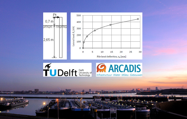
This thesis is a comparison between different geotechnical models which can be used to design single laterally loaded piles. The comparison is useful, because in the daily practice of geotechnical engineering many discussions arise on which model is most suitable in which situation. This is also mainly due to the differences in results between different models. Sharp designs can reduce cost massively.
Of course, in literature several researches were already conducted in comparing different models. However, these comparisons were either theoretical comparisons, or comparisons between a single model and measurements. With today’s most used models, comparisons between the models and measurements have not yet been made. The objective of this thesis is therefore to compare the accuracy of the different models and find recommendations on which model can be used best in which situation.
The problem of a single laterally loaded pile is complex due to the presence of multiple
nonlinearities. Firstly, the soil stiffness is nonlinear. For small deformations, the soil reacts stiffer than for larger deformations. The maximum soil resistance and stiffness increase nonlinearly with depth and depend nonlinearly on the pile diameter. Then, also the mobilization of the soil resistance along the pile develops nonlinearly. The pile deformation at the top is largest, if the load increases on the pile, deeper soil layers become more active.
Eight different models were chosen and compared. These are:
- Blum
- Brinch Hansen
- Broms
- Characteristic Load Method (CLM)
- Nondimensional Method (NDM)
- MSheet
- p-y Curves
- Plaxis 3DFoundation
Measurement and Prediction of Vibrations Generated by Drop Hammer Piling in the Bangkok Subsoils
R.P. Brenner and S. Viranuvut
A large number of vibration measurements on the ground surface and on an adjacent building were performed in connection with the pile driving activities on a site north of Bangkok. Vibration intensity was expressed in terms of peak particle velocity. A statistical comparison with previously collected data from other sites in the Bangkok area revealed that vibrations generated by driving a pile into one of the bearing strata commonly used for foundation piles in this region, i.e., stiff clay or the underlying sand, are not of significantly different magnitude. A previously recommended upper bound for vibrations to be expected could be confirmed. A multiple correlation with penetration data obtained from Dutch cone tests at the site and pile driving records was also attempted but the only variable giving significant contribution was the cone resistance. The correlation, however, was rather weak.
Models for Prediction of Surface Vibrations from Pile Driving
Records
Brent Ross Robinson
University of North Carolina
Master’s Thesis
August 2006
This study compares high strain dynamic testing measurements taken near the top of a driven pile to peak particle velocities on the ground surface and sound levels detected in the air some distance from the pile during driving. Based on a sample of installation records from 16 piles driven at the Marquette Interchange Project in Milwaukee, Wisconsin, a series of peak particle velocity plots versus distance, energy and scaled distance were created using traditional horizontal distance and rated hammer energy. These plots were modified using the seismic distance, the diesel hammer potential energy from the calculated stroke, and the energy transferred to the pile top. Incorporating these measurements tended to reduce some of the scatter in the data. More importantly, it was also discovered that components of peak particle velocity in the ground can be well correlated to the total pile resistance measured by dynamic testing. A plot of total resistance versus depth often independently yields the same shape curve as a plot of at least one component of peak particle velocity versus depth. A simple mathematical attenuation model is proposed as an initial step toward utilizing this relationship to predict at least one component of ground motions. Measured peak overpressure (noise) in the air correlated less directly to the quantities measured on the pile, but a conservative and simple mathematical model can still be proposed based on the dynamic testing-measured velocity near the pile top and idealized sound generation and attenuation theories.
Pile Load Test Report, Interstate 88
Robert McCarty and Robert Houghton
New York Department of Transportation
October 1973
On July 16 through July 18 and July 23, 1973 a Pile Load Test, in accordance with Item 88 PLT as described in the proposal, was performed at the site of the West Abutment of the Eastbound Bridge of Bridge #12, Mainline over the Susquehanna River of I-88, Susquehanna Expressway (PIN 9357.02 311, FISH 72-5). The Pile Load Test was performed on an HP 12 x 53, 26 feet in length with approximately 25 feet in the ground. Two telltales were provided for the purpose of determining the amount of resistance
carried by the tip and by the side of the pile. An H-pile is not usually used as a friction pile, but the soil type encountered at this site would not readily permit the driving of displacement type piles, which are commonly used as friction piles.
This load test consisted of a static load test and two constant rate of penetration (CRP) tests. The purpose of the second CRP is discussed in Appendix A of the report.
Prediction of Pile Set-Up for Ohio Soils
Lutful Khan, PhD, PE, and Kirk Decapite
Cleveland State University
FHWA/OH-2011/3
February 2011
ODOT typically uses small diameter driven pipe piles for bridge foundations. When a pile is driven into the subsurface, it disturbs and displaces the soil. As the soil surrounding the pile recovers from the installation disturbance, a time dependant increase in pile capacity often occurs due to pile set-up. A significant increase in pile capacity could occur due to the set-up phenomenon. For optimization of the pile foundations, it is desirable to incorporate set-up in the design phase or predict the strength gain resulting from set-up so that piles could be installed at a lower End of Initial Driving (EOID) capacity.
In order to address the set-up phenomena in Ohio geology, a research was conducted by compiling pile driving data in Ohio soils obtained from ODOT and GRL, an engineering company dedicated to dynamic pile load testing, located in Cleveland, Ohio. The set-up data of twenty three piles was compiled along with time, pile length, pile diameter. The liquid limit, plastic limit, average clay and silt content, average SPT value were compiled along the pile length. In 91 % cases of the driven piles, some degree of set-up was observed. Correlations among several soil parameters and pile capacities were explored. An equation was proposed between the final and initial load capacities of the piles as a function of time and shown to be in good agreement with the strength gains of driven pipe piles in Ohio soils.
Principles of the axial pile setup
Alexander V. Busch
University of Bremen
April 2022
Piles, as widely used foundations onshore and offshore for advanced structures or wind turbines, are known for their frequently observed, long-lasting capacity increases, known as pile setup. Often this results in a doubling of the pile capacity within the first 100 days after their installation. Many sub-mechanisms are suspected to contribute to this increase, such as changes in the pile surrounding stress field, an aging of the soil, or modifications at the pile shaft surface due to physiochemical processes. However, many of the existing studies focus too much on a single mechanism as a possible cause of the setup. As a result, attempts to transfer these findings to alternative sites and/or piles frequently did not produce satisfying results. The possibility, that this process might be multi-factorial is still often rejected or just ignored. As a result, there is still no conclusive theory to explain the setup in all its facets, even though it was first mentioned now 120 years ago. An improved understanding of the mechanisms and a consequent integration of the setup into daily engineering practice has the potential of considerable cost savings. In particular if smaller, thinner or shorter piles could be used to carry the same loads as before. When piles are used as foundations for wind turbines, eliminating such inefficiencies will be of utmost importance in a world of dwindling resources and for a humanity fighting the climate crisis. The present study aims at improving our understanding of this process in three, well defined sub-studies, which concern one constant test environment. An extensive, small-diameter field study (Chapter 4) reveals that the capacity of a pile and its setup is dependent on the respective installation method as well as on the corrosion vulnerability of the pile material. Piles installed by a rather soil disturbing installation method – i.e. by pile vibration instead of impact driving or pile jacking – potentially tend to a reduced initial capacity, but simultaneously, to a more pronounced setup. It is shown, that vibrated piles can reach capacities of identical impact driven piles after not more than 100 days of aging. Indications are provided, that for longer time ranges the vibrated piles might even outperform these impact driven piles. The second study (Chapter 5) evaluates three-years of capacity monitoring of six, offshore-size piles installed by pile vibration and by impact driving. It demonstrates that vibrated, large-diameter piles provide just a third of the capacity of impact driven equivalents even after an aging period of three years. The small-pile experiment hypothesis is consequently rejected, and a size dependence of the pile setup is assumed. A final laboratory and modeling study (Chapter 6) evaluates the impacts of physiochemical effects on the overall setup. Direct shear testing of naturally-aged surfaces and subsequent capacity modeling indicate that physiochemical effects and the formation of a pile adhering sand-crust have a high potential to increase pile capacity. With these three sub-studies, this doctoral thesis provides a significant contribution to the understanding of the setup as a multi-factorial and multidimensional process.
Procedures for Scour Assessments at Bridges in Pennsylvania
Peter J. Cinotto and Kirk E. White
Pennsylvania Department of Transportation and the U.S. Geological Survey
Open-File Report 00-64
2000
Scour is the process and result of flowing water eroding the bed and banks of a stream. Scour at nearly 14,300 bridges1 spanning water, and the stability of river and stream channels in Pennsylvania, are being assessed by the U.S. Geological Survey (USGS) in cooperation with the Pennsylvania Department of Transportation (PennDOT). Procedures for bridge-scour assessments have been established to address the needs of PennDOT in meeting a 1988 Federal Highway Administration mandate requiring states to establish a program to assess all public bridges over water for their vulnerability to scour. The procedures also have been established to help develop an understanding of the local and regional factors that affect scour and channel stability. This report describes procedures for the assessment of scour at all bridges that are 20 feet or greater in length that span water in Pennsylvania. There are two basic types of assessment: field-viewed bridge site assessments, for which USGS personnel visit the bridge site, and office-reviewed bridge site assessments, for which USGS personnel compile PennDOT data and do not visit the bridge site. Both types of assessments are primarily focused at assisting PennDOT in meeting the requirements of the Federal Highway Administration mandate; however, both assessments include procedures for the collection and processing of ancillary data for subsequent analysis. Date of bridge construction and the accessibility of the bridge substructure units for inspection determine which type of assessment a bridge receives. A Scour-Critical Bridge Indicator Code and a Scour Assessment Rating are computed from selected collected and compiled data. PennDOT personnel assign the final Scour-Critical Bridge Indicator Code and a Scour Assessment Rating on the basis of their review of all data.
Relationships between wall friction, displacement velocity and horizontal stress in clay and in sand, for pile drivability analysis
E.P. Heerema
An instrumented laboratory study of the subject.
Reliability-Based Specification for Driven Piles
Jay A. Berger and George G. Goble
July 1992
Resistance factors for steel, timber and concrete piles as structural members, derived with First-Order Second-Moment (FOSM) methods, and an evaluation of the reliability levels inherent in current design codes are presented. The results are included in a proposed format for a pile design and installation specification offering additional resistance factors reflecting the reliability of the means used to establish installed pile capacity and the construction control procedures employed.
Shaft Resistance of Driven Piles in Clay
D.M. Potts and J.M. Martins, Imperial College, London
In recent years much research effort has been devoted to the development of an effective stress approach to pile design in clays. Although the objectives of such research are simple, the problem has proved to be of such complexity that only limited progress has been made to date. The major problems arise in the prediction of the changes in effective stresses which occur as a result of both installation and the subsequent loading. Much recent work has concentrated on predicting stress changes arising from the installation of, and subsequent consolidation around, driven piles in clay. Much progress has been made in this respect. However the same attention has not been given to the effects of loading such piles after installation.
In this paper the results of a numerical investigation into the mobilisation of shear resistance along the shaft of a full displacement pile are presented. The analysis has considered the behaviour of the soil around a short segment of a very long pile, well away from the influences of both the pile toe and the ground surface. The pile is assumed to have been installed by driving and only loaded after any excess pore pressures have dissipated.
Static and dynamic analysis of an
offshore mono-pile windmill
foundation
L. Kellezi and P. B. Hansen
GEO – Danish Geotechnical Institute
2003
Different foundation concepts have been presented and applied to offshore windmill turbines designed and constructed all over the world. The advantages and disadvantages of different concepts are already outlined and research from universities and private companies continues with this respect. The choice of the foundation concept for an offshore windmill turbine is governed by several factors, which include soil conditions, the water depth at the location, the scour and erosion, the capacity of the turbines, the foundation cost etc. It is investigated that for offshore windmill turbines the foundation costs are approximately 25% of the total cost.
There are basically three types of foundations applied to different windmill parks. These are: gravity based, skirted and piled foundations. Piled foundations are the most common foundations for offshore structures. Driving the piles into the seabed is the standard method of installation. Considering the soil conditions and other factors the mono-pile foundation concept was chosen for the windmill park at Horns Rev, Denmark. Such concept is also applied at Utgrunden and Bockstigen in Sweden and other places. Large diameter mono-piles are generally used for offshore windmill turbines placed at shallow water. A lot of progress has been made in the last decades towards the development of engineering methods for the static and dynamic analysis of the pile foundations. Different approaches can be adopted in solving the problem. The p-y approach or Winkler model, has been widely used to design piles subjected to lateral static or dynamic loading. Based on this approach the lateral soil-structure interaction can be modeled using empirically derived nonlinear springs and dashpots.
Static Measurements of Pile Behaviour
M.T. Davisson
An overview of the subject from the developer of the Davisson Method for interpreting axial pile capacity from static load tests.
A survey of numerical methods in offshore piling
Note: Ian Smith not only surveyed numerical methods, he did a great deal to advance them. His book Programming the Finite Element Method (with D.V. Griffiths) is a classic.
I.M. Smith
1980
Numerical methods have been widely used in the offshore piling industry for the past 25 years or so. This paper cannot attempt to be a literature review, but merely sets out the current state of achievement and tries to point the way to future developments. Topics include four main subject areas; quasi-static behaviour of piles and groups, drivability, pore pressure considerations and dynamics.
Tension Capacity in Silty Clays–Beta Pile Test
J.H. Pelletier and E.H. Doyle, Shell Oil
A summary of a pile test and its results performed in conjunction with the Cognac platform in the Gulf of Mexico.
Testing of drivability of concrete piles and disturbance to sensitive clay
Bengt Fellenius and Laval Samson
The results are reported of an investigation of a group of thirteen 12-inch diameter precast concrete piles driven through 60 ft (18 m) of sensitive marine clay followed by 10 ft (3 m) of silt and sand and 13 ft (4 m) of very dense silt to end bearing in glacial till. The purpose of the test is to study the drivability of the piles through very dense soil and to measure the disturbance caused to the sensitive clay by the driving of displacement piles. The paper presents the soil conditions at the site and the testing program. The test results are discussed and experience gained from the follow-up of the driving of 520 piles at the site is presented. Pile loading tests showed the piles to have an ultimate bearing capacity exceeding 450 tons. It was established that the shaft resistance in the clay during test loading exceeded by 25% the undrained shear strength of the clay as measured by field vane testing. In comparison, an uplift test to failure showed that the uplift shaft resistance along the pile was only 60% of the undrained shear strength of the clay. The pile driving developed large pore pressures in the clay which exceeded the effective overburden stresses. The excess pore pressures dissipated over a period of slightly more than 3 months. Vane testing within the pile group immediately after driving showed that a shear strength reduction of about 15% was caused by the piles..
Upgrade of Axially Loaded Pile-Soil Modeling with the Implementation of LRFD Design Procedure
Mohamed Ashour, Ph.D., P.E., Amr Helal and Hamed Ardalan
University of Alabama at Huntsville
Alabama DOT Contract No. 930-769
February 2012
This report and the accompanying computer code (Software, WBUZPILE) describe the characterization and analysis of piles under axial loads. A combination of different formulas obtained from ALDOT long time experience along with fundamental equations of deep foundations are employed in this program to assess the axial capacity of driven piles. The report focuses on the entry of input data, interpretation of the output results and description of the employed soils and equations. In addition to sand and clay models developed by ALDOT, the report presents modeling formula for silt soils that include sandy silt and clayey silt and weathered rock (soft rock). The current program analysis allows the utilization of the LRFD approach that determines the geotechnical resistance factor based on the calibration by fitting as presented in Chapter 1. In addition to the use of varying values of safety factors and DL/LL, the program user can also use a default resistance factor of 0.71 which is based on a commonly used safety factor of 2 and DL/LL ratio of 2 as recommended by ALDOT. The obtained results are presented numerically and graphically through the output data files and plotted graphs. Several warning messages are built in the program to avoid many of the common mistakes. It should be mentioned that the current version of the program WBUZPILE has the capability of directly uploading the input data files created earlier by the original program BUZPILE with no need for any modifications.
Use of Pile Driving Analysis for Assessment of Axial Load Capacity of Piles
Rodrigo Salgado and Yanbei Zhang
Purdue University
FHWA/IN/JTRP‐2012/11
May 2012
Driven piles are commonly used in foundation engineering. Pile driving formulae, which directly relate the pile set per blow to the capacity of the pile, are commonly used to decide whether an installed pile will have the designed capacity. However, existing formulae have been proposed based on empirical observations and have not been validated scientifically, so some might over‐predict pile capacity, while others may be too conservative. In this report, a more advanced and realistic model developed at Purdue University for dynamic pile driving analysis was used to develop more accurate pile driving formulae. These formulae are derived for piles installed in typical soil profiles: a floating pile in sand, an end‐bearing pile in sand, a floating pile in clay, an end‐bearing pile in clay and a pile crossing a normally consolidated clay layer and resting on a dense sand layer. The proposed driving formulae are validated through well documented case histories of driven piles. Comparison of the predictions from the proposed formulae with the results from static load tests, dynamic load tests and conventional formulae show that they produce reasonably accurate predictions of pile capacity based on pile set observations.


It is good collection of papers on pile capacity calculations and assessment.
LikeLike
Thank you very much.
LikeLike