
For more of this book, click here.
The main method for constructing wells in water depths exceeding 100–150 meters is rotary drilling with clay mud flushing of the borehole. During the development of wells drilled using the rotary method, it is necessary to remove the clay particles of the flushing fluid from the near-filter zone of the aquifer. This is essential to restore the natural permeability of the water-bearing rocks.
The task of restoring the permeability of the filter and the adjacent zone of the aquifer also arises during the operation of water wells when their productivity decreases. This occurs as a result of chemical or mechanical clogging of the screen slots and the water-bearing rock.
When restoring the permeability of the water-receiving section of the well and its near-filter zone—which have become clogged with clay mud during drilling or with chemical compounds and various deposits during operation—a significant effect is achieved through the use of hydrodynamic processing of the well. Several methods of generating hydrodynamic impulses in the wellbore are known: explosive, pneumatic explosion, electro-hydraulic, ultrasonic, and vibratory.
Without resorting to a strict assessment of the comparative effectiveness of known methods of hydrodynamic well processing, it should be noted that the feasibility of implementing one method or another in the practice of water well development and repair is determined by how technologically advanced the method is. It also depends on the extent to which it matches the production conditions of drilling and repair operations. From this point of view, the use of vibratory technology of the vibrational method for generating hydrodynamic pulses in a wellbore is highly practical. This method was proposed by VNIIGS jointly with the “Promburvod” trust.
The vibrational method for treating water wells consists of simultaneously pumping out (flushing) the well or filling the wellbore with a chemical reagent, while exposing the screen and the near-wellbore zone of the aquifer to hydrodynamic pressure. This pressure is generated in the water column by a working element—a tubing string with disks attached to it (Fig. 102)—vibrating along the longitudinal axis of the well.
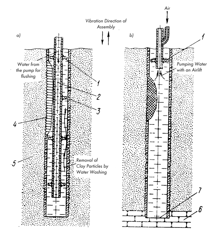
The combined action of alternating hydrodynamic pressure and the flow of water or reagent ensures the effective destruction of the mud cake on the walls of the well and screen during well development. It also effectively removes chemical plugging (clogging) products from the screen and the near-wellbore zone of the aquifer during the restoration of operating well productivity. The vibrational method of well treatment is technologically flexible, allowing for the regulation of both the duration and intensity of the hydrodynamic treatment, and making it possible to combine dynamic and chemical action on the plugging material. By utilizing the vibrating working element, it ensures the injection of the reagent beyond the screen perimeter and its circulation within the treatment zone. Furthermore, if necessary, it allows for well pumping without utilizing traditional water-lifting equipment.
The intensity of mud cake destruction and the rate at which plugging chemical compounds are dissolved by the reagent on the well and screen walls are determined by the hydrodynamic pressure generated in the water by the vibrating working element (Fig. 103). This pressure is characterized by alternating positive and negative pulses.
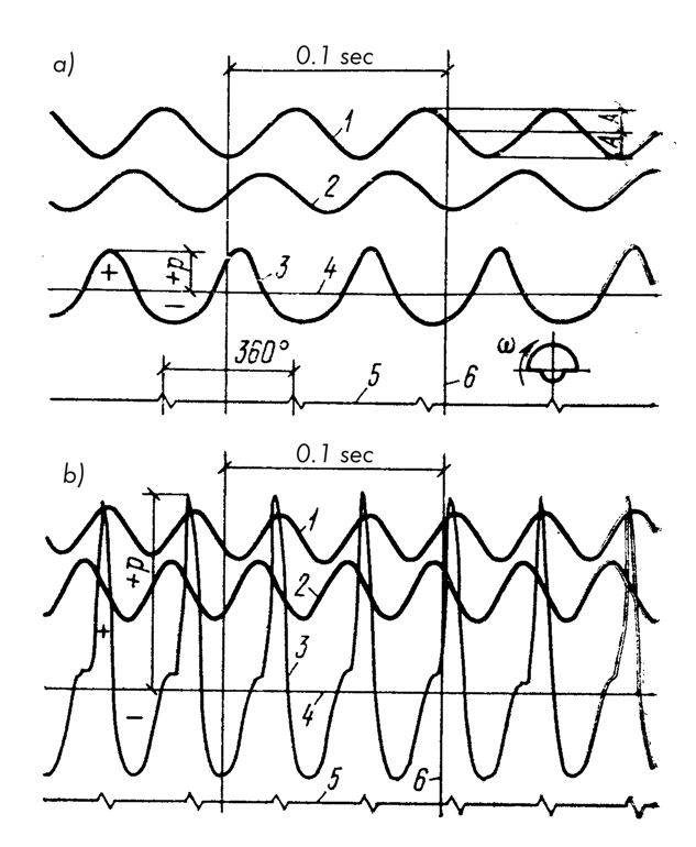
 (a) and
  (b). 1: Displacement of the vibration exciter, 2: Vibration velocity of the vibration exciter, 3: Curve of hydrodynamic pressure generated in the water column by the vibrating working element, 4: Zero line of hydrodynamic pressure, 5: Mark of the position of the vibration exciter’s eccentric weights, 6: Time mark
Research conducted at VNIIGS demonstrated the following:
- Pressure vs Amplitude: At a fixed vibration frequency of the working element, the hydrodynamic pressure amplitude depends linearly on its vibration amplitude (Fig. 104).
- Pressure vs Frequency: At a constant vibration amplitude of the working element, the dependence of the pressure amplitude on frequency takes the form of a resonance curve (Fig. 105).
- Pressure vs Clearance: At constant values of vibration amplitude and frequency of the working element, the hydrodynamic pressure amplitude increases as the radial clearance between the disks and the screen walls decreases (Fig. 104).
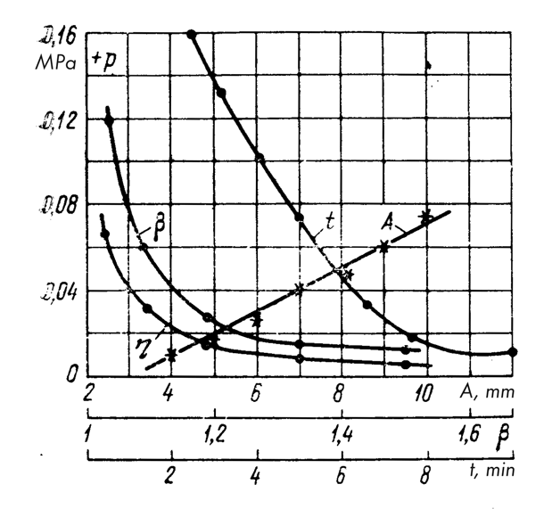
 on the vibration amplitude of the working element
  and on the radial clearance
  between the disks of the working element and the screen walls. Curve 1 shows the dependence of the time required for full restoration of screen permeability on the amplitude of the hydrodynamic pressure.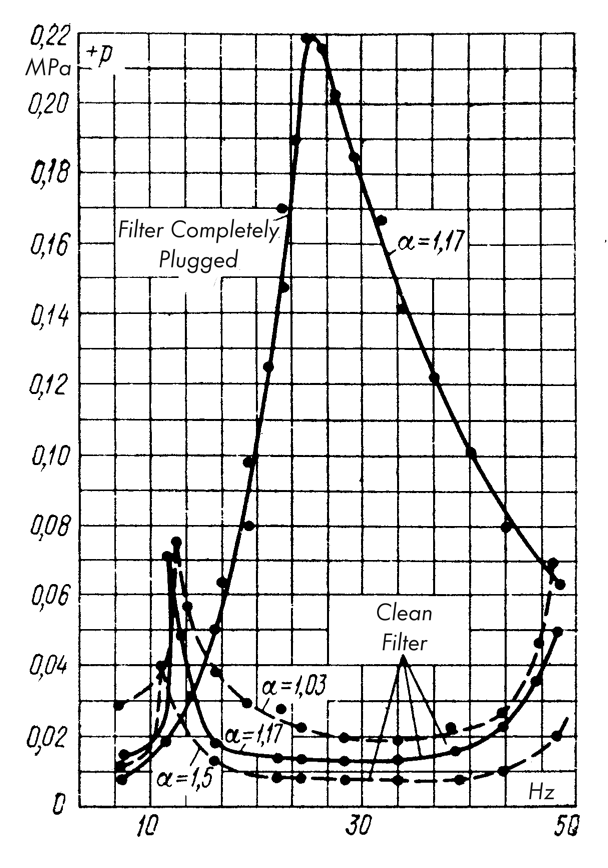
The degree of pressure loss in the clearance is determined by the coefficient 
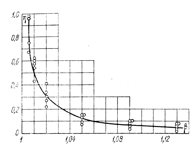 on the magnitude of the radial clearance between the discs of the working tool and the walls of the filter pipe.
The time spent on cleaning the filter decreases with an increase in the amplitude of the hydrodynamic pressure (Fig. 104). It has been experimentally established that during the destruction of colmation (clogging) formations and the increase in permeability of the filter and the near-wellbore zone, the amplitude of the hydrodynamic pressure pulses gradually decreases.
With fixed vibration parameters of the working tool, the minimum value of the pressure amplitude corresponds to the moment of complete recovery of the zone’s permeability. This circumstance is highly important, as it allows, if necessary, to control the progress of the filter and near-wellbore zone permeability recovery by the changes in hydrodynamic pressure amplitude, and to stop vibrating upon completion of the monotonic reduction of the pressure amplitude and stabilization of its value.
Before starting work on the vibrational hydrodynamic treatment of a well, its characteristics, as well as the power of the energy supply source, are known. When calculating the processing parameters, it is necessary to establish the vibration mode of the vibrator and a rational design scheme of the working tool based on these conditions, which would ensure the required value of hydrodynamic pressure.
When treating imperfect wells (Fig. 107a) drilled into low-head, fine-grained water-bearing sands (which are characterized by the formation of a dense mud cake or strong colmation formations on the well walls) and cased with mesh filters, the vibrations of the water column are excited by a single disc.
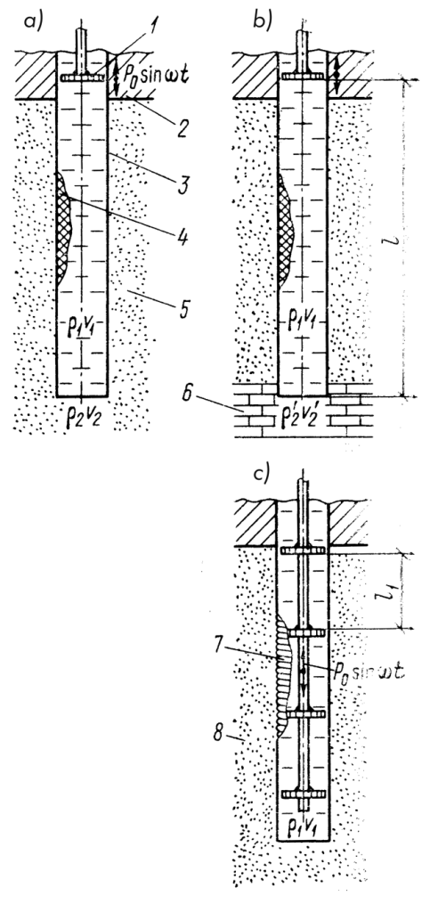
 ), perfect (
 ) wells drilled into fine-grained sands, and also an imperfect or perfect well (
 ), where the water-bearing formation is represented by coarse sand, gravel, or pebbles.
1 – disc; 2 – roof of the water-bearing formation; 3 – filter frame; 4 – mesh covering of the filter; 5 – fine-grained sand; 6 – aquiclude (confining bed); 7 – wire covering of the filter; 8 – coarse-grained sand.
The magnitude of the hydrodynamic pressure 


where 
When treating perfect wells (Fig. 107b) drilled under analogous hydro-geological conditions considered above, the vibrations of the water column are excited by a single disc in the same manner as before. However, in contrast to the scheme in Fig. 107, 
If we consider the vibrations of the water column when operating in a standing wave mode as a system with a single degree of freedom possessing a reduced mass and elasticity, then:

where 


The treatment of wells drilled in unstable rocks, which are characterized by the formation of a loose mud cake on the well walls and the penetration of clay particles and colmation formations into the water-bearing formation over a considerable distance, and cased with wire-wrapped filters (Fig. 107

obtained from the condition of fluid incompressibility. After the destruction of the clay crust or clogging formations, the nature of the hydrodynamic process changes, and

where 

The power required to maintain the selected vibration mode of the drive, kW, is determined by the formula obtained as a result of experimental research:

where 


The outer diameter 

![\sigma = 4 A \omega^2 q l_2 / [\pi g (D_{\text{nar}}^2 - D_{\text{vnu}}^2)],](https://s0.wp.com/latex.php?latex=%5Csigma+%3D+4+A+%5Comega%5E2+q+l_2+%2F+%5B%5Cpi+g+%28D_%7B%5Ctext%7Bnar%7D%7D%5E2+-+D_%7B%5Ctext%7Bvnu%7D%7D%5E2%29%5D%2C&bg=ffffff&fg=333333&s=0&c=20201002)
where 
The safety factor for strength must be taken equal to 2–2.5.
It has been experimentally established that the amplitude of hydrodynamic pressure, which determines the lower limit of effective sediment destruction with minimum energy consumption for driving the vibratory installations, is 0.2–0.3 MPa at an impulse frequency of at least 8.3 Hz. For vibrational hydrodynamic treatment of wells, surface vibratory installations of the VUR type (see Table 15), a working tool, equipment for flushing, or an airlift pump, and, in necessary cases, a chemical reagent, developed by VNIIGS, are required.
The parameters of vibratory installations of the VUR type, the working tools of which, depending on their mass, perform oscillations with an amplitude of 6–12 mm at a frequency of 11.7–13.3 Hz, ensure the excitation of hydrodynamic pressure impulses in the well trunk with an amplitude up to 0.4–0.5 MPa (in wells with a depth of up to 800 m and a filter pipe diameter of at least 114 mm).
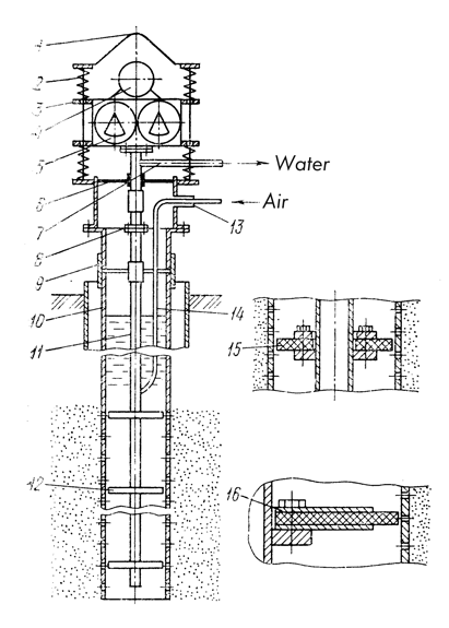
Surface installations of types VUR-2 and VUR-3, the design of which is identical, consist of an eccentric-type vibration exciter and a support frame connected to each other by guide rods and shock-absorbing springs. The drive of the vibration exciters is carried out by a chain transmission from an electric motor installed on the support frame (VUR-3) or on the top cover of the vibration exciter body (VUR-2). The support frame of the vibratory installation is equipped with a water outlet and a rubber diaphragm that allows sealing the wellhead. The support frame is connected to the casing, production, or filter string of the well by interchangeable adapters, which complete the installations, each of which has five adapters for pipe diameters of 219, 273, 326, 377, and 426 mm.
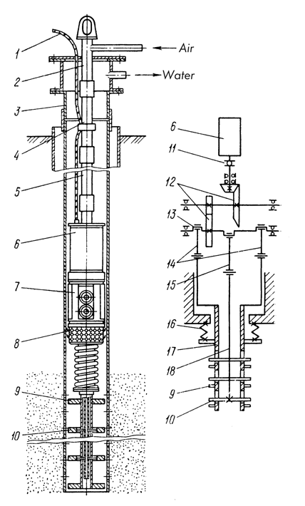
1 — electric cable; 2 — wellhead cap; 3 — production casing string; 4 — drill pipe string; 5 — tubular reservoir for water; 6 — electric motor; 7 — vibration exciter; 8 — air-water mixer; 9, 10 — discs of the working tool connected respectively to the outer and inner pipe; 11 — gear clutch; 12 — block of bevel-cylindrical gears; 13 — eccentric shaft; 14, 15 — connecting rods; 16 — spring; 17, 18 — outer and inner rod, respectively.
The submersible vibratory installation VUR-4 [31] (Fig. 108) consists of a vibration exciter, a drive electric motor, a working tool, a drill pipe string, and a wellhead cap. The kinematic vibration exciter is mounted in a hermetic housing and is driven by a water-filled electric motor.
The bodies of the vibration exciter and the electric motor are provided with a longitudinal internal channel, through which air, necessary for airlift operation, can be supplied to the air-water mixer located in the lower part of the vibratory installation housing.
A downhole unit, unlike surface vibration units, subjects to vibration not the entire string of pipes, but only the working element with discs, which determines its predominant use in wells with a depth of more than 200–250 m, where surface vibration units cannot be applied.
The presence of downhole electrical equipment (motor, cable) excludes the possibility of using the VUR-4 vibration unit during combined vibration-reagent treatments of wells in cases where hydrochloric acid is used as a reagent.
The working element of the vibration unit consists of a pump-compressor pipe with a diameter of 60 or 73 mm, on the lower part of which along a length equal to the height of the filter, with a pitch of 0.5 m, discs with a thickness of 10 mm are attached, the outer diameter of which is slightly smaller than the internal diameter of the filter (Fig. 109a).
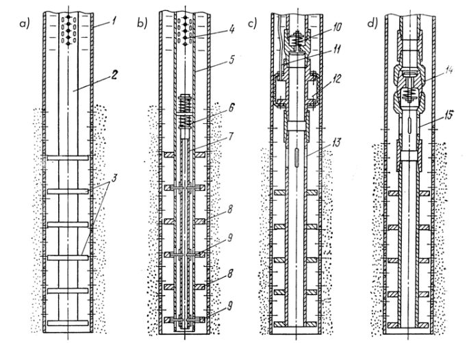
a — with rigidly attached discs; b — with counter-movement of discs; c — with an ejector; d — with a vibro-pump; 1 — filter column; 2 — pipe; 3 — discs; 4 — airlift mixer; 5, 7 — outer and inner pipes; 6 — node of spring suspension; 8, 9 — discs attached respectively to the outer and inner pipe; 10 — valve assembly of the vibro-pump; 11 — hose for supplying compressed air to the rubber bladder; 12 — packer; 13 — openings for reagent release; 14 — valve assembly of the vibro-pump; 15 — suction openings of the vibro-pump.
Discs are made of steel rings, on which shiftable (depending on the diameter of the production string of the well) rubber half-rings are fixed (Fig. 112). The rubber-metallic design of the discs [32] allows for easy mounting of the working element in the well and makes it possible to increase the effect of hydrodynamic action due to the small (1–2 mm) radial gap between the skeleton of the well filter and the outer diameter of the discs.
In a number of cases (clay removal from fine-grained water-bearing sands, combined vibration-reagent treatment of wells during chemical clogging of filters), it is possible to use a working element, the adjacent discs of which perform opposite reciprocating movements relative to each other (Fig. 109b), and for a downhole vibration unit, anti-phase oscillatory movements, ensuring excitation in the water column of hydrodynamic pressure impulses of opposite directions. These impulses help to increase the efficiency of cleaning the filter and the near-wellbore zone of the well.
If necessary, special valve assemblies can be mounted in the upper part of the working element (above the filter), one of which is a vibro-pump (Fig. 109d), ensuring the pumping of water from the well without using traditional water-lifting equipment during its vibrational hydrodynamic treatment.
The vibro-pump is made in the form of a separate assembly, including a housing and a spring-loaded valve, which ensures the passage of liquid only in the direction from bottom to top. The vibro-pump is equipped with a collar and a nipple for connection with pump-compressor pipes.
Depending on the depth of the well and the dynamic water level on the string of pump-compressor pipes of the working element, several vibro-pumps are sequentially installed at intervals of 8–10 m. In this case, the lower vibro-pump pumps water out of the well, and the remaining pumps transfer liquid to the surface through the internal cavity of the working element equipped with a discharge outlet in the upper part. In that case, if during combined reagent treatment of the well the vibro-pumps, compared with the image in Fig. 109d, are mounted flipped by 180°, and in the middle part of the working element bypass windows are arranged, then in the filter zone of the well it is possible to obtain circulation of the reagent, which will help to increase the efficiency of well restoration.
Experience shows that vibro-pumps can pump both clean water and liquid containing a significant amount of suspended particles.
Studies have established that the valve assemblies of vibro-pumps used with VUR-2 and VUR-3 vibration units provide a capacity of up to 
The operating mechanism with a vibration supercharger (Fig. 109b) [35] allows for forced injection of a reagent through a filter into the bottom-hole zone during well treatment. This occurs during its vibro-hydrochemical treatment and achieves a significant effect in restoring the permeability of the bottom-hole zone filter.
The vibration supercharger includes a valve injection assembly and a replaceable sealing assembly—a packer. The packer is equipped with a fitting for supplying compressed air into a cavity. This cavity is formed by the outer surface of the frame and the inner surface of the rubber sleeve. It ensures the sealing of the filter when pressure is created in its cavity that exceeds the hydrostatic pressure at the installation site by 0.2–0.3 MPa. Compressed air is supplied to the packer via a separate hose lowered into the well parallel to the column.
During vibration of the operating mechanism, the supercharger pumps fluid located in the well in a pulsed mode. The fluid moves from top to bottom, thereby creating an excess pressure zone in the treated chemical reagent filter and bottom-hole zone. This significantly increases the penetration radius of the reagent into the formation.
High-performance work production for vibro-hydrodynamic well treatment is determined not only by the level of technology and convenience of the vibration equipment. It also depends on the level of mechanization of all auxiliary and associated operations.
At the same time, drilling and operating organizations do not possess a fleet of specialized mobile units for well development and routine repair work. Therefore, these tasks are carried out using drilling rigs, which in this case are used unproductively. Alternatively, they involve lifting equipment of general utility that does not meet the specific requirements of the work. This necessitates significant labor costs and fails to provide the necessary quality of work and compliance with safety regulations.
VNIIIGIS and the “Promburvod” trust conducted research aimed at developing specialized self-propelled units. These are designed to perform the full complex of tasks during well development for water and their routine maintenance using vibration technology.
The result of this work was the creation of self-propelled, energetically autonomous units ABO-1, ABO-2 (Fig. 110), and AVR-1. These allow for the execution of the following operations during the development of water wells drilled by the rotary method using clay mud, as well as during routine repair of operating wells:
- Vibro-hydrodynamic treatment of the bottom-hole zone and filter in combination with airlift pumping or other methods of water lifting. This includes chemical treatments of wells in case of their clogging by precipitates of chemical origin;
- Tripping operations: performance during installation (dismantling) in the wellbore of working elements, tubing, or water-lifting equipment;
- Submersible pump startup: execution for testing after installation in the well;
- Bailing cleanup: execution of well cleaning operations with a bailer.
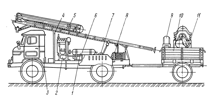
1 — air receiver; 2 — piston air compressor KT-7; 3 — automobile GAZ-66; 4 — support for the mast in transport position; 5 — guy mast; 6 — electric generator ECC-81-6S; 7 — screw jack for the mast; 8 — hoisting winch; 9 — spare wheel; 10 — trailer; 11 — vibration installation VUR-2.
Units (see Fig. 110) are equipped with a cargo winch, an assembly mast, an electric generator with a control panel, and a reciprocating compressor with an air receiver. All mechanisms are mounted on a truck chassis and are driven by its engine. Vibration units VYR-2, VYR-3, or VYR-4 are transported on a single-axle trailer and are driven by the unit’s electric generator.
The assembly mast of the ABO-2 unit, due to its simple transition from transport to working position thanks to a boom outreach of 1.5 m, allows for assembly and repair work on wells where it is impossible to install the unit in the immediate vicinity of the wellhead (see Fig. 111). Depending on the modification, the mast of the ABO-2 unit can have a height of 9 or 11 m from the ground surface to the axis of the crown block 9.
Even more advanced is the assembly mast of the AVP-1 unit, which, with a 14-meter height from the ground surface to the axis of the crown block, has an outreach of 2.2 m, allowing for repair work on wells over which a protective structure is built and where water piping is present. To increase operational safety, this mast is equipped with two additional side supports, as well as an upper platform that is connected with a hinge to the mast and automatically moves into the working position when raised.
Work on the vibration-hydrodynamic treatment of wells during their development begins after the installation of the filter string and the removal of the drilling rig from the wellhead (if a submersible vibration unit VYR-4 is used, this final operation may be skipped).
Vibration-hydrodynamic treatment of operating wells that are clogged with chemical sediments is carried out after partial dismantling of the water piping, lifting the production pump, and, if necessary, cleaning the well with a bailer. All these operations can be performed using units of types ABO and AVP. The working tool in the well and the surface vibration unit on its wellhead are mounted according to the diagram in Fig. 112.
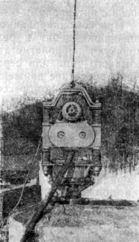
The general view of the VYR-2 vibration unit mounted on a well is shown in Fig. 113.
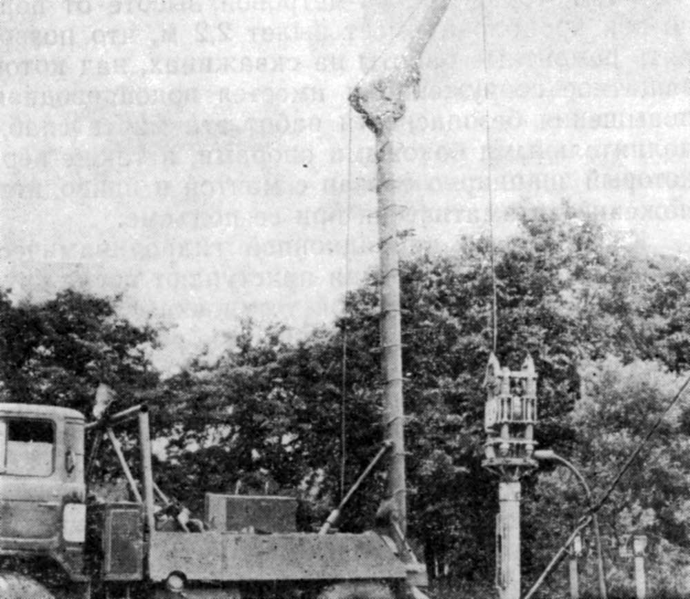
Depending on the purpose of the vibration-hydrodynamic well treatment with surface vibration units (clay destruction of a newly drilled well, restoration of well productivity during repairs without chemical reagents, combined vibro-chemical declogging of the filter and near-wellbore zone), a conventional working tool, a counter-moving disc tool, a vibro-compressor, or a vibro-pump can be mounted in the wellbore (see Fig. 109).
A conventional working tool is typically used during the development (clay destruction) of newly drilled wells, as well as in combined vibro-chemical treatments. During well clay destruction where the aquifer is represented by fine-grained sands, and during vibro-reagent treatments to increase the efficiency of the vibration-hydrodynamic effect, a working tool with counter-moving discs can be used. Vibro-pumps are used in combination with a conventional working tool or with counter-moving discs when clearing newly drilled wells and repairing them in cases of low dynamic levels and low flow rates, as well as when the pumped water contains a significant amount of sand particles. On the tubing string of the working too, it is necessary to sequentially install several downhole vibrators at intervals of 8–10 m.
During the combined vibrochemical treatment of a well with a reduced flow rate due to chemical clogging, vibro-injectors are used in conjunction with a specialized working tool. This tool is generally a disk type with a working element whose disks perform a recurring reciprocating motion. The vibro-injector is mounted on the lower end of the tubing string under the working element with disks. Before lowering into the well, a compressor hose is connected to the mouth of the rubber sleeve of the vibro-injector packer.
A single-disk working tool must be used in cases where it is difficult to lower a multi-disk working tool into the filter zone. In this scenario, to achieve the effect of vibration-hydrodynamic processing, the design of the disk must be rubber-metallic with a minimum (1–2 mm) gap between it and the filter pipe. A single-disk working element is usually placed in the upper, unperforated part of the filter string.
During vibration, mud removal of newly drilled wells and restoration of the productivity of wells subjected to mechanical clogging, the vibration equipment is installed first, and an airlift system is assembled. Then, they begin pumping fluid out of the well with the airlift and periodically turn on the vibro-unit for 3–5 minutes. When pumping resumes after the completion of the vibration-hydrodynamic treatment, the sand and clay content in the water is carefully monitored.
After the water clears up, the vibro-unit is restarted. If the amount of clay and sand particles increases again during subsequent pumping, the pumping is continued until the water clears. Then, the vibro-unit is turned on once more. Vibration-hydrodynamic treatment and pumping are continued until no significant increase in clay particles is observed in the water after the next activation of the vibro-unit.
During the pumping process, after each activation of the vibrator, the well yield is measured, and the dynamic water level is determined according to a known formula based on the readings of the pressure gauge of the airlift system’s compressor.
The above-mentioned duration of each cycle of vibration treatment is determined on the basis of experimental studies. These studies showed that during 3–5 minutes of vibration, the water contained in the wellbore becomes saturated with particles of clay and sand, turning into sludge. To increase the efficiency of further vibration treatment, this sludge must be periodically removed from the well.
On the other hand, it has been experimentally established that such a duration of the cycle of hydrodynamic vibration treatment does not cause a noticeable change in the porosity of the bottomhole zone and does not adversely affect its filtration characteristics.
When using downhole vibrators, hydrodynamic treatment and well pumping are performed simultaneously. The vibro-unit is turned on for 20–30 minutes with intervals of 10–15 minutes.
Combined vibrochemical treatment of wells whose filter and bottomhole zones are clogged with deposits of chemical origin is carried out in the following order. Initially, two to three cycles of vibro-treatment are carried out according to the technology described above, until the water pumped out of the well is relatively clear. Then, through a nozzle usually used to drain water entering from the wellbore, a chemical reagent must be poured into the casing string. The chemical composition of the reagent and its amount are determined depending on the physical-chemical properties and structure of the clogging material.
For the reaction of the reagent with the filter structure, 15–20 minutes are required. Then, the rubber sleeve of the packer is inflated, and the vibrator is turned on for 10 minutes. During the vibration process, hydrodynamic treatment of the filter and the bottomhole zone is carried out simultaneously with the chemical treatment. During the operation of the working element of the vibro-injector, an alternating excess pressure of 0.3–0.4 MPa is created in the treated chemical reagent filter and bottomhole zone.
Upon completion of the first cycle of vibration, the pressure in the packer is released, and the reagent expelled beyond the filter is returned to the wellbore. After 20 minutes, the filter zone is sealed again, and vibration is resumed for 10 minutes. These operations are repeated 3–5 times in the specified sequence. Then a second batch of reagent is poured into the well, and the entire cycle is repeated. After the vibro-reagent treatment, airlift pumping of the well is performed until the solid and gaseous reaction products are completely removed. This technology of vibro-reagent action, developed by VNIIGS and VNIIVODGEO, allows for favorable conditions for the process of dissolving the clogging material by the chemical reagent.
Three technical configurations of the submersible vibro-unit VUR-4 are possible in wells. See diagram Fig. 114a. This layout must be used when there is a low dynamic water level in the well and a small clearance between the body of the vibro-unit and the production casing. The diagram in Fig. 114b should be used in cases where the optimal immersion depth of the airlift mixer is below the location of the VUR-4 vibro-unit. Furthermore, hydro-geological conditions and construction details must be considered for wells to allow removing water and sludge between the production and air columns of pipes. Vibro-treatment of wells in combination with pumping by a submersible electric pump (Fig. 114c) is practical to use in cases where it is impossible to deliver a compressor to the well, as well as with large significant diameters of production casings.
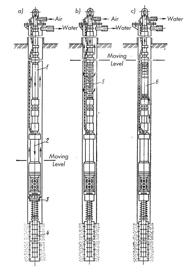
a – at a low dynamic level and using an airlift scheme with a mixer built into the vibration unit body for pumping;
b – at a high dynamic level and with the possibility of well pumping by an airlift with a separate mixer;
c – in the case of using a submersible electric pump for pumping;
1 – drill pipe string;
2 – vibration unit;
3 – airlift mixer in the body of the vibration unit;
4 – vibration working element;
5 – separate airlift mixer installed in the drill pipe string;
6 – submersible electric pump mounted in a hollow frame.
Vibrational hydrodynamic treatment was used by the “Promburvod” trust with a positive result for the development and restoration of several hundred wells. At the same time, the following tasks are effectively solved using the vibration method:
- Development (clay removal) of newly drilled water wells, drilled, as a rule, into water-bearing sands using rotary drilling rigs with the use of clay mud; in this case, due to the use of vibrational hydrodynamic treatment, a reduction in the well development period is achieved, obtaining water extraction from the well required for operation with low labor costs;
- Increasing well productivity on those where, as a result of development by airlift pumping, it was not possible to achieve the planned flow rate; in such wells, the use of vibrational hydrodynamic action allows restoring the permeability of the filter and the near-wellbore zone, increasing flow rate and handing over objects into operation;
- Restoration of productivity of operating wells that have reduced their productivity due to mechanical or chemical clogging (colmatation); experience shows that the use of vibration allows for successful repair work and the removal of colmatant from wells both with the use of chemical reagents and without them; the latter is possible if the clogging compounds are represented by sufficiently loose deposits.


One thought on “Restoring The Productivity Of Water Wells During Their Development And Repair”