
It was previously noted that vibration machines are classified with respect to dynamic action on the element to be driven (extracted) into vibrating drivers, impact-vibrating drivers-impact-vibration hammers, and also combined ones, in which both vibration and impact-vibration modes or their combinations can be realized. In most vibrating drivers and impact-vibration hammers the power of the engine is converted into the energy of mechanical vibrations by means of a centrifugal mechanism with eccentrics.
The arrangement of the shafts in the body of the mechanism, the eccentrics on them and also the specific direction of rotation of the shafts make it possible to obtain a different interaction of the centrifugal forces of the individual shafts with the eccentrics and, consequently, to generate various types of vibrations of the vibration exciter.
As a function of the requirements imposed on the construction of the vibrating machine, determined by its technological purpose, form, dimensions and mass, the shafts of the eccentric mechanism can be horizontal and vertical, coaxial, parallel or mutually perpendicular. The specific direction and synchronism of rotation of the shafts with eccentrics are generally achieved with gears, cylindrical or conical.
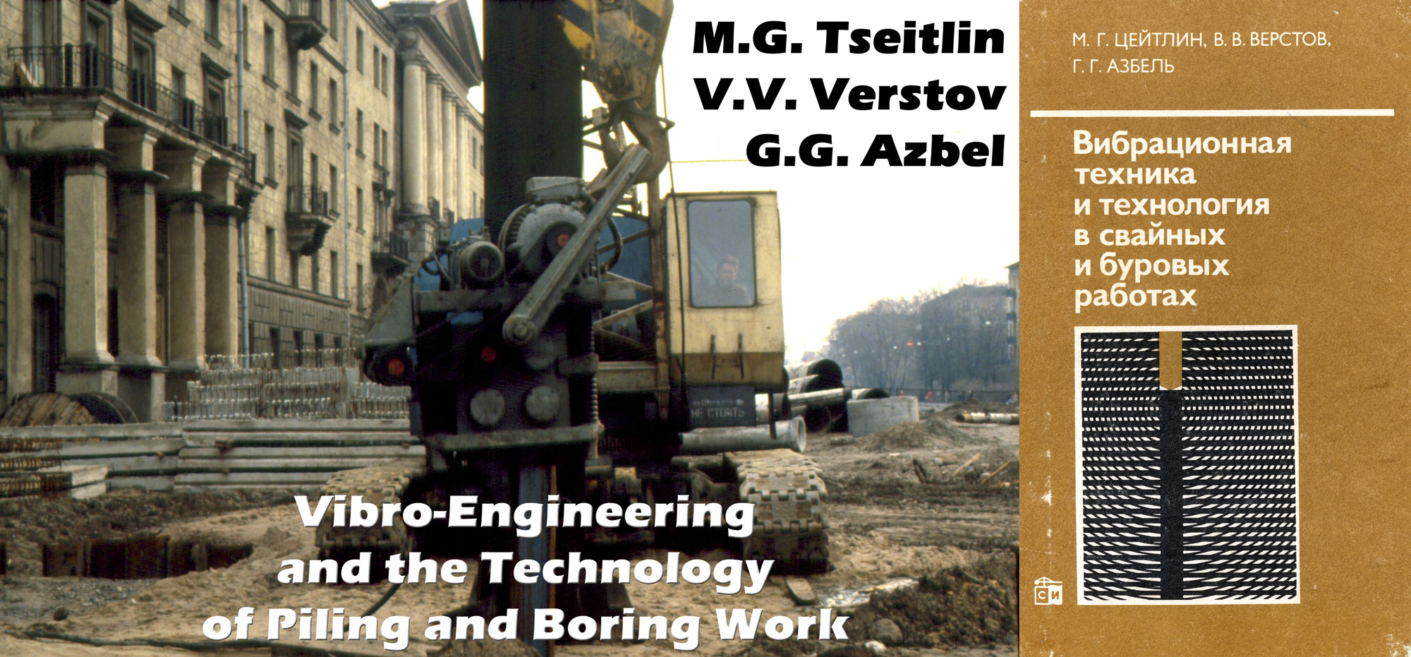
With respect to the longitudinal axis of the element to be driven (extracted), the vibration exciters used in pile-driving and drilling vibration technology are capable of exciting circular, longitudinal, rotational, longitudinal-rotational, transverse and helical vibrations. Various kinematic schemes of eccentric vibration exciters that generate the said forms of vibrations and their combinations are shown in Figure 41. These schemes assume a perpendicular disposition of the longitudinal axis of the element to be driven (extracted) to the plane of the drawing.
As a function of the purpose of the vibrating machine and the type of element to be driven (extracted), the vibration exciter is constructed with the possibility of generating one or more types of vibrations. In the latter case, each type of vibration is used to perform a specific technological operation, for which it is most effective. During the course of the work the vibration exciter can be adjusted to one or the other type of vibration by rearranging the eccentrics by hand on the shafts into the required position or by remote control. Remote readjustment is achieved by changing the original position of the eccentrics on a certain part of the shafts of the vibration exciter through their relative rotation by an angle of 180° /2/.
This apparatus consists of two coaxial interacting elements, one of which is an eccentric carrier and the second has two eccentric stops or supports arranged at an angle of 180°. The carrier and the stops can be on separate disks or in the composition of the shaft, eccentric or gear. The transfer arrangement is placed between the eccentric and the guide link of the kinematic chain (Figure 42) or on the intermediate transmission shaft (Figure 43). Switchover from one type of vibration to the other and vice versa is effected by reversing the drive motor. Part of the eccentrics begins to rotate here only after turning the carriers or stops by 180°; thus, the relative position of all the eccentrics of the vibration exciter and the direction of the resulting compelling forces are changed.

1) longitudinal vibrations;
2) rotational vibrations;
3) disk;
4) disk;
5) stops;
6) carrier.

1) longitudinal vibrations;
2) rotational vibrations;
3) disk with carrier;
4) disk with stops.
In the vibrating drivers and impact-vibration hammers the eccentric mechanism of the vibration exciter is usually driven by electric motors, less frequently by hydraulic motors. Structural solutions of the vibration exciters in which the eccentric shafts are connected with the driving motor by means of a transmission (chain, gear or V-belt transfer). Transmissionless vibration exciters (the eccentrics are mounted directly on the shafts of the drive motor) are basically used for high-frequency impact-vibration hammers (16 Hz or more).
In such vibration exciters of impact-vibration hammers, synchronizing gears are not placed on the shafts of the eccentrics, their synchronous and cophasal rotation is achieved by self-synchronization during the blows of the body of the vibration exciter on the anvil.
In general form, the structural scheme of the vibrating driver for piles, channels, tubes and other analogous elements contains an electric drive motor or hydraulic motor, a vibration exciter of the eccentric type, suspension and cap. Besides, impact-vibration hammers have special collision nodes (limiters) in the form of a block on the body of the vibration exciter, which in this case is called the impact part, and the anvil located on the frame that goes into the composition of the head. In most structural solutions of impact-vibration hammers, springs are placed between the vibration exciter — the impact part and the frame with the anvil by one method or another; the springs serve to regulate the operating node of the impact-vibration hammer in order to increase the stability and effectiveness of the impacts. In a number of cases (the driving of reinforced concrete piles, long casing pipes) devices for transferring a static load (additional load) simultaneously with the vibration or impact-vibration load are provided for increasing the operating effectiveness of the construction of both vibrating drivers and impact-vibration hammers. The series of vibrating machines also contain an electric or hydraulic starting and regulating apparatus.
Both short-circuited electric motors and motors with phase rotor are used as the electric drive motors. The former are used for all types of impact-vibration hammers and also vibrating drivers with relatively low static moments of the eccentric masses. The latter are basically used for heavy-duty low-frequency vibrating drivers with large static moments of the eccentric masses.
In order to increase the service life of vibrating machines (especially impact-vibration hammers) preference should be given to vibration-proof and impact-proof electric motors of the AOPVV type, built into the body of the vibration exciter, in the construction of the drive mechanism with a short-circuited electric motor.
These motors have the evolute parts of the stator windings coated with a special compound and a radial gap between rotor and stator that is enlarged as compared with the standard one. In addition, when they are employed the vibration exciter car be produced in the form of a rigid and reliably operating monoblock and reinforced rotor shaft used in the motor, which in this case is expediently installed on more durable spherical roller bearings.
When a drive with electric motors having a phase rotor is used, it is necessary to employ their type VMT modification, if possible. Such motors have a steel cast body with reinforced brush mechanism and bearings.
Experience in the use of vibrotechnological means revealed that in low-power vibrating drivers (up to 10-15 kW), during the operation of which the generation of impact modes is excluded, the installation of short-circuited electric motors of the usual construction is justified. In this case, if the evolute parts of the stator windings are reinforced in such an electric motor, they can also be successfully used in impact-vibration hammers with a low power (up to 5-7 kW), operating at a frequency of not more than 15 Hz. A classification of the structural solutions of vibration exciters with a eccentric centrifugal mechanism is given in Figure 44.

a) vibration exciters with eccentric centrifugal mechanism;
b) transmissionless;
c) with a transmission;
d) motors mounted in the body of the vibration exciter;
e) motors placed on the body of the vibration exciter;
f) motors placed on a plate fastened to the body of the vibration exciter by springs;
g) moment of the mass of the eccentrics is not realized;
h) moment of the mass of the eccentrics is regulated during shutdowns;
i) the moment of mass of the eccentrics is regulated during operation by remote control;
j) the frequency of the vibrations is not regulated;
k) the frequency is regulated by degrees;
l) the frequency of the vibrations is regulated continuously;
m) body without opening passing through;
n) body with opening passing through;
o) generates one type of vibrations;
p) generates several types of vibrations with manual readjustment;
q) generates several types of vibrations with remote readjustment.
During the driving of reinforced concrete casings to substantial depths, good results in increasing the effectiveness of the process are furnished by the use of TsNIIS vibrating drivers of the VRP type, which assure a regulation of the static moment of the eccentric mass and the frequency of the vibrations during operation.
The technical means for modifying the static moment of mass of the eccentrics are different. In some cases when regulation of the moment by remounting the eccentrics manually during stoppages of the vibration exciter is admissible, the eccentrics are in the form of detachable plates positioned on the arms of the eccentric shafts (for small vibration exciters). In other cases the eccentrics consist of two parts, one of which is fastened rigidly to the shaft, and the other is mounted moveably with the possibility of relative rotation on the shaft with stepped fixation with pins or other method.
In vibration exciters with substantial static moments of the eccentric masses, regulation is effected by shifting the entire eccentric or a part of it in a plane perpendicular to the axis of the eccentric shaft. This shift, which makes it possible to increase or decrease the eccentricity, is accomplished with a screw jack installed in the eccentric, or with the aid of a hydraulic drive. When the latter is used, the static moment of the eccentric mass can be regulated by remote control with the vibration exciter operating.
A stepped regulation of the frequency of the vibrations of vibration exciters mechanically by varying the transmission ratio is rarely used at the present time.
A greater spread is obtained by electrical methods of regulating the drive mechanisms with electric motors, not only with a phase rotor, but also with short-circuiting. This became possible with the introduction of thyristor transducers into practice.
The body of the vibration exciters is either welded or cast. For a number of operations (driving steel pipe or drilling wells, reinforced concrete pile-shells with an open end) it is technologically advantageous to have a central passage opening in the body of the vibration exciter. In such a structural solution of the body it is important to make it sufficiently rigid. When electric motors that are not built in are used, their rigid fastening to the vibration exciter body must be assured. For this, it is necessary to use not only bolt fastening with reliable means against loosening, but also additional snap-on collars that make it possible to avoid breakdowns of the lugs of the electric motor. Two-row spherical roller bearings that are capable of absorbing large radial loads and operating under elastic deflections of the shafts should be used as supports of the eccentric shafts.
Long-term reliable operation of the eccentric mechanism and transmission of the vibration exciter is achieved by an appropriate taking into account of the acting forces and moments from both the drive and the dynamic loads, caused by the nature of the vibration or impact-vibration modes, during the construction stage (see Section 11).
Figure 45 depicts some structural schemes of vibrating drivers used in pile driving and drilling operations. The possible variants of making up the vibration exciters and also the solutions for the suspension of the vibrating machines are evident from the scheme. The greatest spread in practice was obtained with vibrating drivers of the transmission type. As a rule, drivers with a vibration frequency of more than 16 Hz are constructed according to the scheme of a vibrating driver with a spring-mounted load, proposed by 0. A, Savinov and A. Ya. Luskin /3/.

1) transmissionless vibrating driver with separate shock absorber and rigid load-absorbing element;
2) vibrating driver with transmission and built-in electric drive motor and shock absorber with rigid load-absorbing element;
3) vibrating driver with spring-mounted load, ordinary electric drive motor and a rigid load-absorbing element;
4) vibrating driver with built-in electric drive motors, central passage opening and flexible load-absorbing element.
The advantages of this scheme should include the possibility due to the additional non-inertial load of assuring an optimal specific pressure on the soil under the end of the driven element and, as a . result, an increase in the efficiency of its operation, and also the mounting of the electric drive motor on a spring-mounted base.
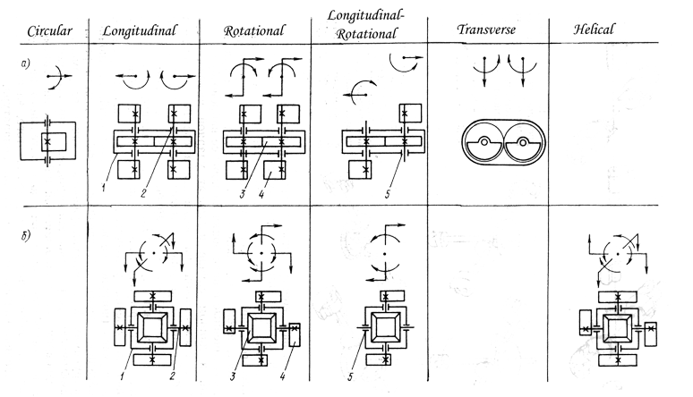
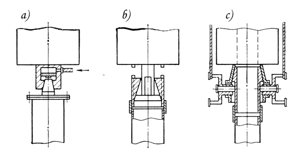
Impact-vibration hammers constructed according to the schemes shown in Figure 46 were used in pile driving and drilling operations. Free springless impact-vibration hammers /4/ (Figure 46a) are currently made low-frequency, primarily heavy-duty ones; they are constructed on the basis of vibration exciters with transmissions. During the operation of these impact-vibration hammers it is difficult to assure a stable operating regime over the entire range of driving the element into the soil. The principal advantage of such impact-vibration hammers resides in the technological simplicity of their use, since they do not require a rigid fastening to the element to be driven. Impact-vibration hammers with springs, set up according to the scheme of Figure 46b /5/ and also impact-vibration hammers for impact-vibrational of piles and tubes from the soil (scheme of Figure 46c) are produced with a vibration frequency of 16 Hz or higher in both transmission and transmissionless types with heads that basically assure a rigid fastening of the impact-vibration hammer frame to the element to be driven.
The peculiarity of impact-vibration hammers with springs in comparison with springless one consists in the fact that they make it possible through regulation of the degree of spring tensioning to obtain a broader range of stable operation and also to vary the operating regime — to change the frequency of the impacts and the impact velocity, An important parameter for adjusting a impact-vibration hammer with springs to one operating mode or the other is also the gap between the hammer head and the anvil. In impact-vibration hammers with a double-deck system of spring installation (see Figure 46b) the mass of the impact part is absorbed by the springs. Therefore, there is the possibility of installing the impact part relative to the frame in such a way that in the position of static equilibrium between the hammer head and the anvil it is possible to achieve a positive gap (distance between the hammer head and anvil less than the amplitude of the forced vibrations), a zero gap (hammer head and anvil come in contact without clearance) or a negative gap (some clearance is produced upon contact of the hammer head with the anvil).
In the double-deck system of impact-vibration hammer springs according to Figure 46b, a rigid fastening to the element to be driven is required, which leads not only to technological difficulties, but also to the need for producing structurally complex and heavy-duty heads, the mass of which seriously worsens the ratio of the masses of the impact part and the element to be driven (extracted) with the head and, as a result, leads to a decrease in the impact efficiency.
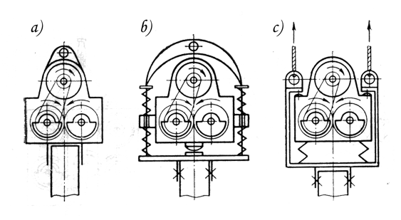
Free spring-mounted impact-vibration hammers, the schemes of which are given in Figure 47, are devoid of the said shortcomings. The difference in the impact-vibration hammers according to the schemes of Figure 46b and 47, a consists in the fact that the second, proposed in VNIIstroidormash, having the advantages of springed impact-vibration hammers, does not require a rigid fastening to the driven element. This is achieved by providing the impact-vibration hammer with a heavy-duty head in the form-of a steel casting, inside of which a reducer with anvil and guide socket for the pile is moveably installed. The mass of the steel casting is determined from the conditions of its lack of movement under the reaction of the springs during the upward movement of the vibration exciter. However, such a free springed impact-vibration hammer has substantial dimensions and total mass, nor does it permit regulating the mode of its operation by varying the tension of the springs during the driving of the pile or tube into the ground.

a) free springed impact-vibration hammer without regulation of the spring tensioning during its operation; free springed impact-vibration hammers with regulation of their operating mode by varying the tension of the springs with a static load;
b) force of the load applied to the vibration exciter and is transferred to the driven element during the impact;
c) the force of the load is applied to the vibration exciter and is transferred to the driven element initially only during the impact, and in the concluding stage of the driving—additionally to it in the form of a constant-acting driving force;
d) the force of the load is constantly applied to the driven element and the vibration exciter, as the element goes deeper there is the possibility of increasing its driving force with a simultaneous decrease in the load on the vibration exciter and an increase in its impact velocity.
The free springed impact-vibration hammers developed at VNIIGS, the schemes of which are presented in Figure 47b-d, do not have such shortcomings. The first of these schemes (Figure 47b) was proposed in Ref. 6 for driving piles with the aid of a movable apparatus; the construction elements of the latter were used for applying the load and absorbing the reactive forces. This scheme, in which the force of the load is applied to the vibration exciter and transfered to the driven element during the impact, was developed and actualized in a free springed impact-vibration hammer for driving pipes in drilling operations /7/. In the latter case the tensioning of the springs during the driving of tube is accomplished by the block and tackle system of the drilling frame and is regulated within the specified limits by a traction windlass, adjusted to operation in an automatic “switching in/switching out” mode. During operation, such a impact-vibration hammer initially has a small negative gap (clearance), which is increased by tensioning the springs with an increase in resistance to driving, which in the necessary cases makes it possible during the driving of tube to preserve a stable regime of impacts of the impact-vibration hammer with periods of “an impact per revolution”.
A further improvement in impact-vibration hammers constructed according to Figure 47b was the scheme depicted in Figure 47c /8/. In the latter, the compression force of the springs in the initial stage of tube driving is realized and regulated just as in Figure 47b, and in the final stage, due to the presence of an additional support frame and stops on the cables in the construction, it facilitates a static pressing in of the tube in conjunction with its driving with the impact-vibration hammer, adjusted during driving to operating in a stable regime with a sufficiently deep negative gap. Such a joint action is quite effective in driving tube to substantial depths.
The block and tackle system of the free springed impact-vibration hammer, constructed according to Figure 47d, /9/ assures the application of the load to both the vibration exciter and to the driven element. It is possible with such a block and tackle system, as the element goes deeper and the resistance to driving increases, to increase the force of its static sinking (the compression force of the lower springs increases) with a simultaneous decrease in the load on the vibration exciter (the compression force of the upper springs decreases). Thus, with an increase in the force of static driving of the element into the soil an increase in the impact velocity of the hammer head of the vibration exciter on the anvil is assured arid, consequently, the energy of ~he impacts. The most rational area of application of the scheme of Figure 47d is the impact-vibrational machines of devices designed for the driving of tubes with a closed lower end during the production of some types of special construction work (trenchless pipe laying, installation of anchors in the ground).
The structural schemes of vibrational and impact-vibrational machines of combined action have specific properties that make it possible to use these machines in such a way that in order to execute a specific technological operation it is possible to establish the most rational type of dynamic action for the specific case. One of the combined vibration machines is the vibrating driver /4/, the basic scheme of which is depicted in Figure 41b; with an appropriate rearrangement of the eccentrics it generates longitudinal, rotational, longitudinal-rotational and helical vibrations. Such a vibration exciter scheme, based on four intersecting shafts with eccentrics, joined at the center with synchronizing gears, is used in the construction of the vibrating gripper with a longitudinal-rotational action /2/ (Figure 48). The distinguishing characteristic of this immersion instrument, designed for processing the soil and the sinking of wells for construction purposes, using mobile load-lifting means, consists in the fact that it permits the sinking of a soil sampler into the ground and unload it with the involvement of longitudinal vibrations most effective for it, and effect the stripping of the core relative to the solid mass of the soil ana the extraction of the soil sampler with the involvement of rotational vibrations. Passage of the vibrations of the vibrating gripper from one type to another is effected remotely by the device mounted in it, as described above (see Figure 42). The constructions of some modifications of vibrating grippers with a longitudinal-rotational action were worked, out at VNIIGS, the vibration exciter of which has shafts with eccentrics arranged parallel in pairs in a vertical plane, and a transfer mechanism for varying the vibration mode is installed on the vertical transmission shaft /10/ (see Figure 43).

1) body of the vibration exciter
2) soil sampler
3) partition wall
4) electric drive motor
5) synchronous conical gears
6) shaft
7) eccentric
8) transfer mechanism
In order to broaden the range of utilization of the vibrating gripper with a longitudinal-rotational action toward more compact soils, a construction of it was worked out in which the soil sampler is sunk into the ground under an impact-vibrational regime and is extracted under rotational vibrations /11/. A special feature of such a vibrating gripper consists in the coupling of the vibration exciter and the driven element by means of sleeves and guide rods, the fitting of which is with a small clearance, and also in the set of springs that are capable under compression of creating clearance at the hammer head-anvil contact.
In this solution, the vibration exciter during adjustment to longitudinal vibrations operates in the mode of a springed impact-vibration hammer with a negative gap, and under rotational vibrations imparts vibrational-torsional movements to the soil sampler in the horizontal plane.
In this case, if the vibration exciter adjusted to operating in the mode of longitudinal-rotational vibrations by a method analogous to that described is coupled with the tubular element to be driven, it is possible to obtain a combined dynamic action, in which longitudinal impacts in conjunction with rotational vibrations will be transfered to the tube. A special transfer mechanism /12/ that assures its adjustment to the mode of longitudinal-rotational vibrations or longitudinal impacts in conjunction with rotational vibrations is proposed for remote control of the operating modes of such a combined impact-vibration machine.
Other examples of impact-vibration machines with a combined action can be the structural schemes of mechanisms given in Figures 49 and 50. The first of them is a springless impact-vibration hammer with a multi-impact action, in which several differently oriented impact pulses in the longitudinal and rotational directions are imparted to the element to be driven (extracted) during one revolution of the shafts with eccentrics /13/. The vibration exciter of such a impact-vibration hammer operates in the mode of longitudinal-rotational vibrations, during which its hammer heads effect consecutive impacts on the anvils of the frame after each 90° of revolution of the eccentrics: a longitudinal impact downward, a rotational impact clockwise, a longitudinal impact upward, a rotational impact counterclockwise, etc. With an increase in the gaps between the hammer heads and the anvils to values that assure an impactless operating mode of the mechanism in specific directions, it is also possible to obtain a single-impact operating mode in the downward direction, two-impact in the downward and upward directions and three-impact in the downward direction, rotational clockwise and counterclockwise.

1) vibration exciter with electric drive motor;
2) enveloping frame;
3) hammer head of longitudinal impacts;
4) hammer head of longitudinal impacts;
5) hammer head of rotational impacts;
6) hammer head of rotational impacts;
7) anvil of rotational impacts;
8) anvil of rotational impacts;
9) anvil of longitudinal impacts;
10) anvil of longitudinal impacts;
11) guide rod (rigidly fastened with the vibration exciter and installed with a sliding fit in the enveloping frame).
The second scheme (Figure 50) assures the operation of the impact-vibrational machine, designed primarily for extracting tubes and piles from the ground /14/. A special feature of such a vibrating machine consists in the fact that impacts directed upward or alternately upward and downward (after 180° revolution of the shafts with eccentrics) can be imparted to the element to be extracted as a function of the degree of prior compression of the springs. A stable and effective operation of the impact-vibration hammer during the extraction of elements from the soil in the regime of two impacts per revolution of the shafts with eccentrics is assured in this case if the pressure of the springs is set so that there is a zero or negative gap between the hammer head and anvils that transfer upward-directed impacts to the tube or pile, and a positive gap, the size of which is 50-70% the amplitude of the vibrations of the vibration exciter, is obtained between the hammer head and anvils for the downward impact.

A common important characteristic of the said structural solutions of the impact-vibration hammers of multi-impact action is that they have a high stability in preserving the established impact-vibrational mode with a significant frequency of the vibrations. This is achieved in that an additional impact (in the direction opposite the performance of “useful” work) assures the stability of movement of the impact part, in which case the stability effect of the “two impacts per revolution of the shaft of eccentrics” mode increases with an increase in the frequency of the vibrations of the vibration exciter.
On the whole, vibration and impact-vibration machines with a combined action broaden the ranges of rational application of the means of vibration technology in pile driving and drilling operations, making it possible to create efficient vibration technologies.
The suspension or support of vibrating drivers and impact-vibration hammers (see Figures 45 and 50) assures their gripping and holding by load-lifting means. Besides load-gripping elements, shock-absorbing elements are a component part of the suspension, usually compression springs that assure the insulation from vibration of the arms and masts of the load-lifting mechanisms during operation of the vibrating machines.
Special technical means developed in recent years serve to increase the operating efficiency of the spring-mounted shock absorbers. They include the system of dynamic braking of the electric drive motor of the vibrating machines, which assures a shortening of the running down time of the eccentric mechanism of the vibration exciter during shutdowns and eliminates the resonant oscillation on the springs of the shock absorber of the body of the vibrating machine (VNIIGS),and also the system of dynamic extinction of the vibrations (DISI). These systems permit a safer application of vibrating machines during the extraction of piles and tubes from the ground with the aid of boom cranes (for more details, see Section 14). An increase in operating safety is also obtained with the signalization and safety devices built into the springed shock absorbers that record the propagation in them and operate when the springs of the shock absorber are compressed to a boundary value.
An important component of vibrating drivers and impact-vibration hammers is the head, which serves to fasten the vibrating machine to the element to be driven (extracted). The structural solution of the head should satisfy two basic conditions: reliably joining the vibrating machine with the element to be driven (extracted) in all its modes of operation and requiring the shortest possible time in performing the fastening and detaching operations with a minimum of labor, while observing the safety regulations required in these cases In some types of pile driving and drilling operations the efficiency of construction of the head and the simplicity of its application frequently predetermine the effectiveness of application of vibration technology.
As a function of the type of operation and the type of element being driven, the heads can be free or assure a rigid coupling of the vibrating machine. In the latter case, the heads can interact during the fastening process with the pile or tube through wedge pairs, special fixing components, passing through the body of the element to be driven (extracted) or by means of friction (adhesion) of the jaws with the surface of this element. The drive of the head mechanism can be manual, with the cable of a load-lifting device, hydraulic and, more rarely, electric.
The oil reservoir of the hydraulic drive can be mounted directly on the vibration machine, or can also be separate, connected to the vibrating machine by hoses. A classification of the heads used in pile driving and drilling vibration technology is given in Figure 51 and examples of the structural designs of heads of various types and different purposes are given in Figures 52-54.

a) heads of vibrating drivers and impact-vibration hammers;
b) they assure fastening on the upper end of the driven element;
c) they assure fastening on the outer surface of the driven element;
d) flange heads with bolt fastening;
e) with free guide heads without fastening (only for impact-vibration hammers);
f) conical heads with stock component fastened to the driven element;
g) with fixing components, moving in a transverse plane through the driven element;
h) with jaws interacting by friction (adhesion) with the driven element;
i) without a drive;
j) with a drive;
k) manually;
l) from the cable of a load-lifting device;
m) hydraulically;
n) electrically.
a – head for driving reinforced concrete piles and pile shells:
b:- head for extracting casing pipes;
c – head for driving and extracting casing pipes.
wedge head for a pile;
b) hydraulic head for a pile, steel pipes and shells;
c) wedge head of vibrating gripper with a longitudinal-rotational action (the wedge pairs are conditionally shown, in the scheme turned by 90°).

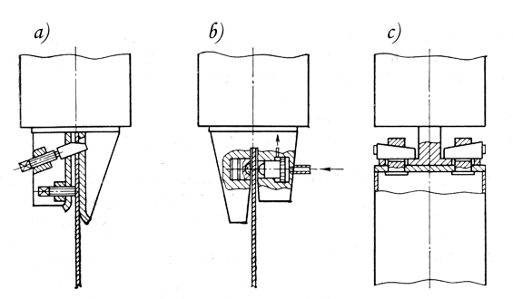
The conical heads (Figure 52) consist of two basic components -conical seat and shaft, one of which is rigidly joined to the bottom of the vibrating driver and the other is also rigidly joined to the element to be driven by some method or other prior to beginning the operation. Heads of this type are used for driving reinforced concrete piles, shell .piles and the driving and extraction of casing pipes. The head (Figure 52a) /15/ was developed for heavy-duty low-frequency vibrating drivers of reinforced concrete piles and shell piles and has self-braking conical pairs that wedge up under the action of the mass of the vibrating driver. For unwedging the head after the completion of driving, the driving transverse wedge or hydraulic drive pi-ton-plunger shown in the Figure is used. The disadvantage of this head consists in the considerable difficulty involved in the preliminary connection of the conical shaft to the reinforced concrete element, usually done by bolt fastening.
The conical heads do not have a marked shortcoming in the driving and extraction of threaded casing pipes with a coupling on one of the ends, because in this case the connection of the conical seat or shaft with the element to be driven is easily done by screwing them into the coupling of the tube.
The conical heads for casing pipes have two variants. In one of them (Figure 52b) /16, 17/ the conical seat with longitudinal grooves is screwed into the coupling of the pipe to be extracted and then the shaft of the vibration exciter, in the form of conical and cylindrical sections, is lowered into it. After the integration of the interacting conical segments of the two components during the raising of the vibration exciter and tensioning the system of extracting static force, the head is wedged. With the completion of of the extraction cycle during operation of the vibration exciter due to the action of inertial forces, an unwedging of the head takes place and it automatically returns to the position in which the shaft freely moves cut of the seat during the following raising of the vibration exciter.
The second variant of the head of this type (Figure 52c) /18/ assures not only extraction, but also driving of casing pipes. This is achieved due to a forced locking of the wedged position of the head by means of eccentric sleeves, which are placed on the axes of the sh&ft that is screwed into the sleeve of the tube and interact with the support surfaces of the conical seat joined with the vibration exciter. Not only a fixation of the head, but also its forced unwedging are achieved by turning the sleeves in a specific direction, The cables of a load-lifting device are used to rotate the sleeves in one direction or the other; they are hooked to levers connected with the sleeves. An important feature of the head examined is the possibility of its use with vibration exciters, in the body of which there is an opening that passes through.
The wedge head for a pile (Figure 53a) is one of the first solutions of a rapid-acting unit for connecting the vibrating driver with the element to be driven. A head of this type was developed by D. D. Barkan and V. K. Typikov in 1949 and then improved by 0. A. Savinov and A. Ya. Luskin. This construction was quite successful and has been widely used in pile driving operations by the vibration technology with the aid of high-frequency, relatively light-weight vibrating drivers. The need for effecting a notch or groove in the pile and also the involuntary weakening of the connection during vibration and the possibility of the development of undesirable impacts at wedge-pile or vibration exciter-pile contact should be considered the disadvantages of the wedge head of this type.
The head for a pile, developed at TsNIIS /19/ and depicted in Figure 53b, is equipped with a punch-die pair and a hydraulic drive. The pile is clamped with local deformation of its wall. This is a reliable gripping system; in the construction of the he.ad, however, it is necessary to have sturdy plates and jaws, capable of absorbing reactive forces from the deformation of the pile wall. The head shown schematically in Figure 53c is used in VNIIGS for joining the body of the vibration exciter of a vibrating gripper with a longitudinal-rotational action with the soil sampler. It consists of four tangentially arranged lugs belonging to the soil sampler, into which wedges are driven in pairs to meet each other. Such a connection permits a reliable transfer to the soil sampler of not only longitudinal vibrations, bu~, also a torsional moment of the compelling force during rotational vibrations.
In the heads with clamping jaws the basic condition of their reliable operation is that the frictional force created at the jaw-driven element contact point have a value that would exceed at least the lateral resistance of the pile or tube in all the stages of its sinking into the soil and, in the best case, the amplitude of the compelling force of the vibration exciter. VNIIGS, TsNIIS, VNIIstroidormash, TsNIISK and a number of other organizations worked on the development of heads in which the pile or pipe is clamped by several jaws moved by movable wedges. A. bolt-nut pair (Figure 54a), the cables of a load-lifting device, reducer with electric drive and hydraulic drive were used for moving the wedges. Such heads were designated as a rule for the vibration driving of reinforced concrete piles and pile shells and also steel pipes, i.e., elements having developed outer surfaces. Multi-jaw heads of various construction are complex in working principle, have substantial masses and dimensions, and do not have a high operational reliability, therefore, they have enjoyed limited application in pile driving and drilling practice. On the basis of experience accumulated on their development and use. effective heads with a hydraulic drive were developed. They are depicted in Figure 54b and c, and clamp the wall of the driven element (pile, steel pipe or shell) between two jaws, one of which is connected to the drive and the other is a stop.
The advantage of the structural solution of the head (Figure 54b) as compared with other clamping devices cf the jaw type consists in the fact that it is equipped with a hydraulic accumulator that prevents weakening of the grip during the operation.
Depending on their technological purpose, vibrating drivers and impact-vibration hammers used in Soviet pile driving and drilling practice can be divided into several groups. The names and technical characteristics of the vibrating machines contained in each of them are given in Tables 9-16. Table 16 contains a list and brief technical characteristics of power-operated vibration apparatuses specialized for certain types of work and used in the Soviet Union.
The vibrating drivers of various reinforced concrete elements (Table 9) are multi-shaft vibration exciters driven by electric motors with a phase rotor and with heads of the flange, conical or multi-jaw types.
| Parameters | LIIZhT | TSNIIS | ||||||
| VP-1 , SP-42A | VP-3, VP-3M | VPM-170 | VP-80 | VU-1.6 | VRP-15/60 | VRP-30/132 | VRP-70/200 | |
| Type of pile to be driven and its maximum dimensions in a plane, m | Piles, 0.4 x 0.4; Pile shells, 1.0 dia. | Piles, 0.45 x 0.45; Pile shells, 1.2 dia. | Pile Shells, 2.0 dia. | Pile Shells, 1.6 dia. | Pile Shells, 1.6 dia. | Piles, 0.45 x 0.45; Pile shells, 1.2 dia. | Tubular piles, 0.6 dia.; pile shells, 1.2 dia.; 1.6 | Pile shells 1.6 dia. and 3 in paired operation |
| Depth, m Diameter of the straight through opening, mm | 15 | 20 | 25 | 15 | 25 1360 | 15 | 25 | 40 |
| Rated power of the electric drive motor, kW | 60 | 100 | 160 | 100 | 150 (75 x 2) | 63 | 132 | 200 |
| Static moment of the mass of eccentrics, kg . cm | 9300 | 23,600 | 51,000 | 27,500 | 34,500 | 0-15,000 | 0-30,000 | 23,000-70,000 |
| Frequency of the vibrations, Hz | 7 | 6.8 | 6.8; 7.7; 9.1 | 6.8; 7.7; 9 | 8.3 | 0-7.8 | 0-8.7 | 0-8.3 |
| Maximum amplitude of the compelling force, kN | 180 | 442 | 1700 | 900 | 958 | 342 | 889 | 1900 |
| Total mass, kg | 4500 | 7500 | 12,300 | 9,000 | 11,600 | 5000 | 7,250 | 13,000 |
| Overall dimensions, mm; in a plane; height | 1300 x 1240 2100 | 1560 x 1540 2500 | 1260 x 1860 3400 | 1950 x 1450 2430 | 2618 x 3350 1910 | 1240 x 1000 2040 | 1440 x 1440 2240 | 1700 x 1600 3500 |
Vibrating drivers of various reinforced concrete elements (Table 9) are multi-shaft vibration exciters with a drive by electric motors with a phase rotor and with heads of the flange, conical or multi-jaw type.
The impact-vibrational machines of VNIIstroidormash and TsNIIS for driving and extracting piles (Table 10) are spring-mounted impact-vibration hammers. The impact-vibration hammer VI-601 and its modifications are free, spring-mounted according to the scheme of Figure 47a. The schemes of Figure 46b or 46c pertain to the other impact-vibration hammers of these organizations that require rigid coupling of the impact-vibration hammer with the pile, which is accomplished in the case of SP-58 with a wedged head, and hydraulically for MSh-2M, designed according to the scheme of Figure 53b.
| Parameter | VNIIstroidormash | TsNIIS | VNIIGS | |||||
| Machine | VI-601 VI-633 VI-644 | SP-58 | VRP-3/44 | MSh-2 MSh-2M | VPP-2A V-401 V-401A | V-401B | VSh-1 VSh-1M | VP-1U |
| Function | Driving | Extraction | Driving | Extraction, Driving | Driving, Extraction | Driving, Extraction | Driving, Extraction | Driving |
| Maximum length of the pile, m | 15 | 10 | 15 | 15 | 12 | 12 | 20 | 20 |
| Rated power of the electric drive motor, kW | 44 (2 x 22) | 15 (7.5 x 2) | 44 (2 x 22) | 44 (2 x 22) | 55 | 45 | 44 (2 x 22) | 60 |
| Static moment of the mass of the eccentrics, kg . cm | 2000 | 420 | 2500, 3000, 3500 | 920, 1130 | 1000 | 1100 | 2500 | 9300 |
| Frequency of the vibrations (impacts), Hz | 8 | 8 | 0-16 | 16 | 16, 25 | 22 | 13, 16, 20 | 7 |
| Maximum amplitude of the compelling force, kN | 218 | 100 | 360 | 96, 134 | 250 | 220 | 400 | 180 |
| Force of the total compression of the shock absorber springs, kN | – | – | – | 250 | 120 | 120 | 290 | – |
| Type of head | Free | Wedge | Hydraulic | Hydraulic | Wedge Hydraulic | Hydraulic | Wedge Hydraulic | Free |
| Mass of the impact part, kg | 2100 | 700 | – | 2000 | – | – | 3000 | 7000 |
| Total mass, kg | 7300 | 1500 | 3000 | 4200 | 2300 | 2200 | 5000 | 7000 |
| Overall dimensions, mm: in a plane, height; | 1470 x 1130 3000 | 1030 x 720 2700 | 1600 x 9201 1800 | 1210 x 1175 2290 | 1270 x 800 2250 | 1550 x 1160 2590 | 1280 x 1250 2740 | 1300 x 1240 2600 |
Remarks:
- VPP-2A, V-401, V-401A, V-401B and V5P-3/44— vibration machines; VSh-1 and VSh-1M — vibration machines with readjustment to the impact-vibration mode when required; other machines — impact-vibration machines.
- V-401B is equipped with a dynamic braking system for the electric motors.
The VPP-2A vibrating drivers and their modifications are designed according to the scheme of Figure 45c with spring-mounted load, the VSh-1 vibrating apparatus is a vibrating machine with a combined action and is capable of operating in the vibration and in various impact-vibration modes (single-impact and dual-impact, as in pile driving and in its extraction) /45/. These vibrating machines are supplemented with heads according to the schemes of Figure 53a or Figure 54b.
The vibration apparatuses FVN-1, PYK-2 and PVN-2B are vibration machines with a combined action, generating the types of dynamic action shown in Table 11. A vibration exciter of longitudinal-rotational vibrations, coupled with the plate of a flanged head, is used in the PVN-1 vibration apparatus for the transition from the mode of longitudinal-rotational vibrations to the mode of longitudinal impacts in conjunction with rotational vibrations there is a special apparatus, which is a worm-screw mechanism with manual or electric drive. The vibration apparatuses PVN-2 and PVN-2B are designed for driving large-diameter pipes open at the bottom, and their extraction. They include four vibration exciters with circular vibrations, installed on a common frame and interconnected by a system of mechanical synchronization. The first of these machines has a straight-through opening and a wedged head, similar to that depicted in Figure 53c; the second is without a straight-through opening and is equipped with a head having two hydraulic holding devices, according to the scheme of Figure 54b.
| Indices | PVN-1 | PVN-2 | PVN-2B |
| Maximum depth, m | 18 | 20 | 14-18 |
| Diameter of the tubes, mm | 377, 426 | 720, 1020 | 720, 820 |
| Type of action during driving | longitudinal-rotational vibrations or longitudinal impacts in conjunction with rotational vibrations | longitudinal-rotational vibrations | longitudinal vibrations |
| type of action during extraction | longitudinal-rotational vibrations | longitudinal-rotational vibrations | rotational vibrations |
| Diameter of the straight through opening, mm | – | 920 | – |
| Rated power of the electric drive motor, kW | 60 | 68 (17 x 4) | 68 (17 x 4) |
| Static moment of the mass of the eccentrics, kg . cm | 6000 | 10,000 | 6500 |
| Frequency of the vibrations, Hz | 8.7 | 8.3; 10 | 12 |
| Maximum amplitude of the compelling force, kN | 180 | 400 | 375 |
| Maximum amplitude of the torsional moment or torque of the compelling force, kN . m | 40 | 200 | 190 |
| Force of the total compression of the shock absorber springs, kN | 190 | 190 | 190 |
| Type of head | Flange | Wedge | Hydraulic |
| Total mass, kg | 5000 | 5500 | 6000 |
| Overall dimensions, mm: in a plane, height | 1650 x 1300 3100 | 1990 x 1950 1660 | 2140 x 2100 3700 |
All the vibrating grippers are vibration machines with a combined longitudinal-rotational (PV-530, PV-820) or longitudinal-transverse (PV-380, TV-1D) action and have the characteristics given in Table 12.
| Indices | PV-380 | PV-530 | PV-820 | TV-1D | UVB-1 |
| Capacity of the soil sampler, m3 | 0.16 | 0.35-0.6 | 0.75-1.1 | 1.5 | 1.0 |
| Transverse dimension of the soil sampler, mm | 380 dia. | 530-720 dia. | 820-1020 dia. | 600 x 1600 | 920-1220 dia. |
| Mean rate of driving into the soil, m/min | 0.8 | 1.0 | 1.0 | 1.0 | 0.5 |
| Rated power of the electric drive motor, kW | 11 | 22 | 22 | 22 | 22 |
| Static moment of mass of the eccentrics, kg . cm | 600 | 1000 | 2400 | 3250 | 2000 |
| Frequency of the vibrations, Hz | 15.2 | 16.6 | 13 | 11.3 | 10 |
| Amplitude of the compelling force, kN | 60 | 110 | 160 | 165 | 80 |
| Amplitude of the torque of the compelling force, kN/m | — | 16 | 28 | — | — |
| Force of the total compression of the shock absorber springs, kN | 62 | 90 | 190 | 180 | 100 |
| Mass without soil, kg | 1000 | 1300 | 3000 | 4750 | 3090 |
| Overall dimensions, mm: in a plane | 380 | 530 | 820 | 600 x 1600 | 920 |
| Height with soil sampler, mm | 3950 | 2950 | 3100 | 3750 | 3000 |
Remarks:
- PV-530 and PV-820 — longitudinal-rotational devices of vertical design
- PV-380 and TV-1D — longitudinal-transverse devices of vertical design
- UVB-1 — impact-vibrational devices of horizontal design, with the possibility of self-propulsion to the end face with a rate of approximately 15 m/min.
The impact-vibration apparatuses, the characteristics of which are contained in Table 13, are spring-mounted impact-vibration hammers. UWGP-400 and UVA-1 are constructed according to the scheme of Figure 47d; UVVGP and UVG-1 operate in a horizontal plane in the laying of pipelines, and UVA-1 in the inclined plane in the laying of ground anchors.
| Indices | VNIIGS | MINKh and GP | |
| Machine | UVVGP-400 | UVA-1 | UVG-51 |
| Maximum length of pipe driving, m | 50 | 20 | — |
| Angle of inclination of the pipes to the horizon, deg. | 0 | 0-45 | 0 |
| Maximum diameter of the pipes, mm | 426 | 89 | 529 |
| Length of the pipe sections, m | 8 | 2 | — |
| Rated power of the electric drive motor, kW | 22 | 15 (7.5 x 2) | 75 |
| Static moment of the mass of the eccentrics, kg . cm | 2500 | 800 | — |
| Frequency of the impacts, Hz | 10 | 13.3 | 10 |
| Amplitude of the compelling force, kN | 100 | 57 | — |
| Pressing-in force, kN | 300 | 40 | — |
| Mass of the impact part, kg | 2240 | 650 | 2500 |
| Total mass of the apparatus, kg | 10,000 | 6000 | 6300 |
| Overall dimensions of the apparatus, mm: | |||
| Length | 14,700 | 7700 | 4000 |
| Width | 3200 | 1930 | 2000 |
| Height | 1260 | 4500 | 1630 |
NOTE:
- UVVGP-400 and UVG-51 — for the laying of pipelines.
- UVA-1 — for ground anchor arrangements.
The structural feature of the vibrating machines, the characteristics of which are given in Table 14, consists in the fact that all of them, with the exception of V-108 and BVS-1, have a central straight-through opening. The impact-vibration hammer S-835 is constructed according to Figure 46b, and BVS-1 according to the schemes of Figure 47b and c. The vibrating driver VO-10 and the impact-vibration hammer S-835 have heads according to the scheme of Figure 54a; the impact-vibration hammer BVS-1 for driving pipe is equipped with a head of the free type, and for their extraction in the vibration mode, with a head according to Figure 52b. The vibrators VPF-1 and VPF-2 have heads according to the scheme of Figure 52c.
| Parameter | NIIOSP | Gidroproyect | VNIIstroidormash | VNIIGS | ||
| Machine | V-108 | VO-10 | S-835 | BVS-1 | VPF-1 | VPF-2 |
| Maximum depth of the wells, m | 60 | 50 | 60 | 100 | 40 | 60 |
| Diameter of the pipes, mm | 219 – 426 | 168 – 273 | 168 – 273 | 273- 630 | 168 – 325 | 219-426 |
| Diameter of the straight through opening, mm | — | 305 | 300 | — | 250 | 350 |
| Rated power of the electric drive motor, kW | 28 | 20 (10 x 2) | 15 (7.5 x 2) | 22 | 15 (7.5 x 2) | 24 (12 x 2) |
| Static moment of the mass of the eccentrics, kg . cm | 3000 | 570 | 420 | 2500 | 800 | 1300 |
| Frequency of the vibrations (impacts), Hz | 13.3 | 20 | 12 (i = 2) 8 (i = 3) | 10; 11.7; 13.3 | 13.3 | 13.3 |
| Maximum amplitude of the compelling force, kN | 210 | 92 | 100 | 178 | 57 | 93 |
| Force of the total compression of the spring-mounted shock absorber, kN | — | 100 | — | 216 | 120 | 200 |
| Type of head | flanged | wedge | wedge | free, wedge | wedge | wedge |
| Mass of the impact part, kg | — | — | 700 | 2400 | — | — |
| Total mass, kg | 1600 | 1700 | 1100 | 2400 | 880 | 1500 |
| Overall dimensions, mm: in a plane | 960 x 920 | 1710 x 1100 | 880 x 720 | 880 x 870 | 960 x 600 | 1230 x 690 |
| Overall dimensions, mm: height | 1470 | 1940 | 1120 | 1640 | 1400 | 1570 |
Remarks:
- S-835 and BVS-1 — impact-vibration machines, the others — vibration machines.
- BVS-1 in driving can operate in the mode of a free impact-vibration hammer or free spring-mounted impact-vibration hammer with a maximum tensioning force of 96 kN; in extraction, in a vibration mode.
The vibration exciters of the vibrating devices VUR-2 and VUE-3, the technical characteristics of which are given in Table 15, are mounted by means of shock-absorbing springs on rigid frames with flanged heads, designed for their rigid connection with the filter column of the well. In the VUB-2 the electric drive motor is mounted on the vibration exciter, and in the VUR-3 it is located on the frame and connected with the shaft of the eccentrics by a chain horizontal transmission.
| Indices | VUR-2 | VUR-3 | VUR-4 |
| Maximum depth of the well processed, m | 120 | 250 | 800 |
| Minimum diameter of the working column of the wells,mm | 168 | 168 | 219 |
| Maximum mass of the working element, kg | 1000 | 2000 | 400 |
| Rated power of the electric drive motor, kW | 7.5 | 13 | 5.5 |
| Static moment of mass of the eccentrics, kg . cm | 800 | 1500 | — |
| Amplitude of the vibrations of the working element at its maximum mass, mm | 6 | 5 | 7 |
| Frequency of the vibrations, Hz | 11.7 | 11.7 | 13.3 |
| Maximum amplitude of the compelling force, kN | 435 | 820 | 180 |
| Mass of the vibration exciter, kg | 450 | 600 | 240 |
| Mass of the apparatus without working element, kg | 800 | 1300 | 240 |
| Overall dimensions, mm: in a plane height without working element | 780 x 510 1300 | 1400 x 680 1200 | 188 dia. 3260 |
NOTE:
- VUR-2 and VUR-3 — surface devices with eccentric vibration exciter.
- VUR-4 — driving device with vibration exciter of the kinematic type.
The special feature of the vibrating apparatuses of the VUR type is that after they are mounted on the well they operate in a stationary manner and are dismounted after vibrational hydrodynamic processing of the well and its pumping out. In this connection the shock absorbing springs of the apparatuses should be minimally rigid if possible in order to prevent the transfer of vibrations to the structural elements of the well.
The data of Table 16 illustrate specific examples of the aggregation variants of some types of vibration and impact-vibration mechanisms with basic self-propelled machines, as contained in Figure 2. A more detailed description of the vibrational self-propelled units is given in Sections 17 and 27.
| Parameter | Orgenergostroi | TsNIIS | Glavtonnelmetrostroi | PNIIS | VNIIGS | |||
| Machine | VVPS-20/11M | UVVS-60/10 | — | AVSE-U | OIT-1 | AVB-2m | AVO-2, AVR-1 | AVS-1 |
| Purpose | Driving reinfoirced concrete piles 30 x 30 cm, length 8 m; loosening of frozen soil | Driving reinforced concrete piles 40 x 40 cm, length 12 m | Establishment of leader wells 426 mm dia., depth of 6 m under the pile; driving reinforced concrete pile 30 x 30 cm, length of 7.5 m | Driving of pile foundations with a mass up to 2500 kg under the poles of a contact network | Extraction of casing pipes 114-630 mm dia. from water-lowering wells with a depth up to 50 m; driving of pipe 114 mm dia. with a closed end up to a depth of 25 m | Drilling of engineering-geological wells 200 mm dia. up to a depth of 20 m | Utilisation and repair of water wells with a depth up to 120 m | Driving of reinforced concrete posts for enclosures 18 x 18 cm, with a length of 4 m |
| Base | Tractor T-100M | Tractor T-100MB | Tractor D-804 | Tetraxial railroad platform | Caterpillar truck | Automobile GAZ-66 | Automobile GAZ-66 | Excavator ETU-354 |
| Load-lifting apparatus | Collapsible three-dimensional stand | Swivelling three-dimensional stand | Collapsible frame with brace | Extensible boom | Swivelling tubular stand | Swivelling tubular stand | Swivelling tubular stand with extending boom | Rigid stand |
| Electric power supply | DVS-electric generator | DVS-electric generator | DVS-electric generator | Rolling electric power plant with DVS and electric generator | Power supply system | DVS-electric generator | DVS electric generator; power supply system | DVS-electric generator |
| Vibration Equipment | Special vibrating driver | Special impact-vibration hammer | VMS-1 impact-vibration hammer | VP-1 vibrating driver | Impact-vibration hammer BVS-7 | Impact-vibration hammer VB-7 | Vibration apparatuses VUR-2 and VUR-4 | Special impact-vibration hammer |
| Operation conducted with vibro-technology | Driving of the pile and loosening the frozen soil | Driving of the pile | Driving and extraction of leader pipe, driving of the pile | Driving of piles | Driving and extraction of pipes | Processing and extraction of the soil | Hydrodynamic processing of the filter and the near-driving zone of the wells | Driving the posts of an enclosure |


7 thoughts on “Vibrating Drivers and Impact-Vibration Hammers”