

Background
The Foster hammers are an interesting part of Vulcan’s last years. The concept was to produce a vibratory hammer under a “private label” arrangement, a novelty for the pile driving equipment industry at the time (although the “Chimag” diesel hammers were a similar concept.) In the early 1990’s Vulcan produced several vibratory hammers for the sheet pile supplier L.B. Foster, merging Foster’s own exciter technology (which was Japanese in origin) with Vulcan’s power pack improvements after parting ways with HPSI.
The purpose of this article, however, is primarily to discuss hydraulic vibratory hammers with an emphasis on the “hydraulic.” Pile driving equipment in general and vibratory pile driving equipment in particular poses challenges for the equipment designer and manufacturer. The emphasis here will be on the hydraulics, which are in some ways typical of mobile hydraulics and in some ways unusual. We will use the Foster 4200–the largest of the hammers Vulcan produced–as an example.
Basics of Fluid Power
Fluid power is an important component of power transmission for many mechanical applications. Broadly fluid power can be broken down into two parts: industrial and mobile applications. The emphasis here will be on the latter. Most construction machinery manufactured today has some hydraulic control or power included in the equipment. The original vibratory hammers, designed and produced in the then Soviet Union, were electric, but with the introduction of hydraulic vibratory drivers in the 1960’s today most are hydraulic.
The concept behind fluid power is simple:
- A flow of fluid is pressurised.
- The fluid is delivered to where it is needed.
- The fluid does its work, and is depressurised in the process.
- The fluid, at or near atmospheric pressure, returns to where it is pressurised.
- The process is repeated.
Since the hydraulic fluid being used (petroleum-based, plant-based, or even water) is virtually incompressible, considerations such as occupy students of thermodynamics are not an issue here, although they appear in other parts of the hydraulic system. The power being delivered at any point by a fluid power system is the product of pressure and flow, thus

where 


Both the flow and pressure of the fluid are generally delivered by pumps. Fluid power is a little different from many pumping applications in that the pumps are almost always positive displacement, to insure the accuracy of the flow and pressure. The pump performs the first step of the process outlined above; if the power is transmitted at the other end in a rotary way, a motor performs the third step. Unsurprisingly hydraulic pumps and motors are basically mirror images of each other; their construction is similar (not necessarily identical) and their operation is similar. There are several types of hydraulic pumps and motors in use; we’ll concentrate on piston motors and pumps for two reasons:
- These are what were used in the Foster 4200 and all of Vulcan’s high pressure machinery (more about pressure levels later.)
- They’re a little easier to visualise if you’re not familiar with the application.
Let’s look at a cutaway pump/motor.

The large bronze barrel in the centre of the motor has a series of holes in a radial pattern, into which the pistons (those small cylinders with the rounded left ends) are inserted. The plate an an angle to the bronze barrel is the swash plate, which (through the other plates) either drives (motor) or is driven by (pump) the spline at the left end of the motor, which connects to whatever the motor is driving or the pump is being driven by. The angle between the barrel and the swash plate alows the pistons to move in the barrel, much like the pistons in an automobile do. The displacement per piston is given by

where 


where 

The flow of the pump or motor is given by

where 

where 
The simplest configuration of a pump or motor is a fixed-displacement. In this the angle between the barrel and the drive spline (or keyway) is fixed and thus the stroke
However, there are good reasons for varying the displacement–and thus the flow output–of a hydraulic pump. The pump shown above has a mechanism on the right which varies the position of the right end of the barrel, and thus the displacement of the pistons. Although it’s possible to vary this control manually, the mechanism shown does so by measuring the pressure of the hydraulic fluid, and thus is referred to as pressure-compensated. We’ll come back to why that’s important later.
One further thing that complicates the equations above is leakage around the pistons. Because of the speed of their movement, most piston pumps and motors–and for that matter most hydraulic motors, pumps and valves–do not use seals in them, but tightly fit the pistons or valve spools to the barrel or valve body and allow some leakage. Although this may seem inefficient, the small oil flow allows for lubrication of the components and cooling of the pumps and motors without the drag that seals would induce. This reduces the flow available for power transmission, and the ratio of the ideal flow to the flow actually available after leakage is referred to as volumetric efficiency. This can vary for a number of reasons, but for piston motors and pumps such as we are dealing with here a volumetric efficiency of 90% is a good estimate.
Overview of the Foster 4200
A general overview of vibratory hammers, their theory and application, is given in the monograph Vibratory and Impact-Vibration Pile Driving Equipment. Without going into the detail of that monograph, the following illustrates the basic components of the system.

The exciter does the work of the system by inducing a vertical, sinusoidal force in the pile, which sinks by its own weight. The eccentrics producing this force are turned by a motor, which is driven by a pump on the power pack through the hoses. The pump in turn is driven by a diesel engine, which is the prime mover of the system. There’s also a clamp to hold the driver to the pile; in reality there are two hydraulic systems, one for the motor and one for the clamp. This allows us to illustrate hydraulic systems with both rotational output (the motor) and translational output through a cylinder (the clamp.)
The exciter for the 4200 is shown below. If you’re interested in details on this unit, including the specifications, you can download the Foster 4200 Field Service Manual, First and Second Units.
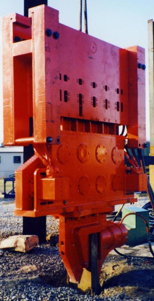
The 4200 has two motors to drive its eight (8) eccentrics, but in this case only one clamp for sheeting. A hose layout for the exciter is shown below.
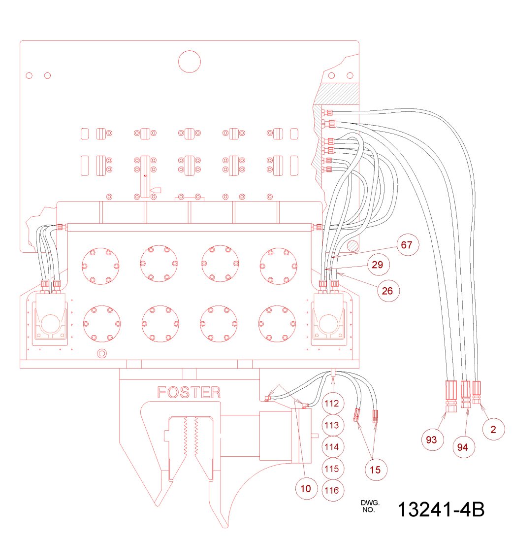
The supply hose is the hose which carries the pressurised oil to the motors. The return hose carries the depressurised oil back to the power pack. The case drain hose returns the leakage from the motor (see earlier comments on volumetric efficiency) back to the power pack. In some cases the return hose can be used as a case drain hose, but in this application there is too much back pressure. The two clamp hoses are bi-directional, as we will discuss shortly.

Until 1991 Vulcan purchased its power packs from HPSI, which used an air-over-hydraulic control system. In going to electric-over-hydraulic, Vulcan was more in line with its competition such as ICE and APE.
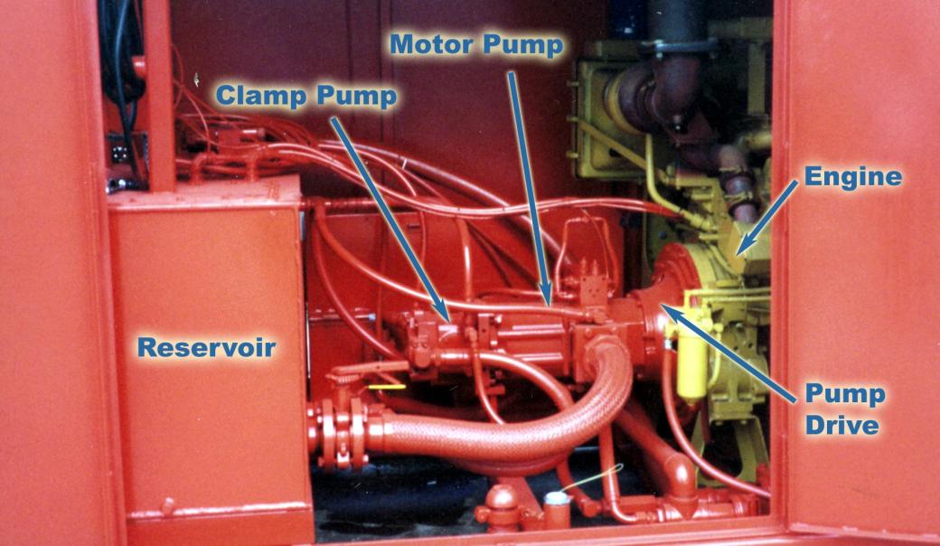
Older hydraulic systems used several types of transmissions between engine and pumps, including power-take-off (PTO) drives. Vulcan used a direct drive which was basically a thin circular plate which transmitted torque from the engine to the pump shaft. This seriously reduced mechanical inefficiencies in the system.
We can thus see the essential components of the hydraulic system:
- Prime mover (4).
- Pump to pressurise the oil (6,7)
- Equipment to do the work and depressurise the soil (motors, clamp)
- Cooling and oil storage (1,15) after oil is returned to the power system.
Pressure in Hydraulic Systems
Fluid power systems are designed to deliver an oil flow at a given flow rate. So what pressure does this come at? This is a key point in fluid power systems: pressure is determined, without any other restrictions, by the load itself. This is true whether the load is rotational or translational, and in this system we have both.
Rotational (Motor) Loads
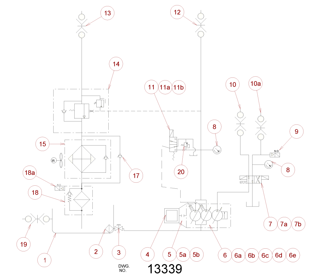
The main pump (6) is configured to, at maximum displacement, deliver a given flow of oil. This in turn determines the rotational speed of the motor. The power put into the system–a product of the pressure and the flow–varies with the load of the system, and that in turn varies with the pressure. So are there limits to that pressure?
The answer is obviously yes. Hydraulic systems, broadly, divide themselves into two pressure ranges: high and low. Low pressure systems generally have their pressure limited to about 2500-3000 psi, and a wide range of hydraulic systems operate in this range. High pressure systems run around 5000 psi and beyond. Each system has its own standard of components. The Foster 4200, in common with Vulcan’s 2300 and 4600 vibratory drivers, was a high pressure unit.
So how do we limit the pressure? In “classic” systems such as the HPSI power packs Vulcan started with, there was a fixed displacement pump and a relief valve (11). When the pressure reached the system maximum, the hammer would slow down and the excess oil would “dump over relief.” This worked, but it generates a lot of heat, which means that the system’s thermal protection shuts it down in short order.
On this hammer, Vulcan used a pressure-compensated, “load-sense” system, which required a special relief valve which, in turn, informed the pump that maximum pressure had been achieved. The pump would reduce its displacement as described earlier until the flow and pressure were balanced. There was still a relief “just in case” for safety purposes, but much of the dumping over relief was eliminated. This also enabled the operator to slow the hammer down without slowing the engine down, allowing the engine to operate in its best torque range.
Translational (Cylinder/Clamp) Loads
Before we describe the hydraulics, let’s look at what the clamp does. Some types of hydraulic clamps are shown below (from this article.)
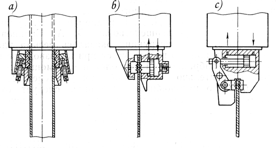
Fun fact: Foster started this project using the clamp type (c), which they inherited from the Japanese. This clamp was common when cylinders were not large and the lever action was needed to obtain the force, but these clamps were heavy. Vulcan convinced them to convert to type (b), albeit without the accumulator, which had been a U.S. industry standard for a long time. Vulcan also convinced Foster to adapt an integral clamp cylinder as opposed to the bolt-on types which are still common on American vibratory equipment.
The clamp is simple: the clamp in pressure is applied to the large (head) end of the clamp and the jaws close on the pile, clamping the pile and stopping the cylinder. When driving is finished, pressure is applied to the small (rod) end of the clamp and the jaws open. The speed of the movement either way is computed as follows:

where 
So what happens then? The system “deadheads,” and, with a fixed displacement pump, most everything goes over relief, with the usual heating problems. There are ways of getting around that but here again pressure-compensated pumps are the best answer, going to nearly zero flow when the clamp deadheads.
Another fun fact: In adopting Vulcan’s clamp design, Foster also incorporated Vulcan’s safety check valve in the clamp, which continued pressurisation in the event the clamp hose was cut. Foster also incorporated Vulcan’s interlock that made it impossible to start the hammer until the exciter was clamped to the pile. That’s one reason why a separate hydraulic system is needed for the clamp; another is that full clamp force and pressure is guaranteed, whereas with the pump for the motor the pressure varies.
Conclusion
We’ve covered a lot of ground here. Hopefully you’ve gotten a better idea of what hydraulic systems in general–using a real-life application–are all about. Vulcan’s effort with Foster’s vibratory hammers was a unique one, and probably resulted in the best vibratory driver (if not the most economical to produce) Vulcan ever made.


how much does it costs ? http://www.google.com
LikeLike