

Webmaster’s Note
This article is an extract from the above referenced book, published in the Soviet Union in the mid-1980’s. It is a valuable document, containing information about vibratory hammers (Soviet and otherwise) not found anywhere else. But some explanation is necessary on the text.
The book itself was furnished by Lev V. Erofeev, the author of this section. The translation was commissioned by Vulcan Iron Works in the late 1980’s.
Although the information is valuable, the editing of the Soviet original is of poor quality, so much so that I told Mr. Erofeev that his editor must have been drinking a lot of vodka when putting the book together. In this edition I have tried to eliminate some of the more egregious howlers (such as confusing millimetres with metres) but the reader should take great care.
The Savinov and Luskin method shown at the end of the text is given in a possibly more understandable form in my monograph Vibratory and Impact-Vibration Pile Driving Equipment. Of course, it is shown by its original authors here.
Some of the equipment described in this monograph–and also some Russian diesel hammers–are shown in the video below, taken in Lyubertsy, outside of Moscow, in December 1992. The various types and models of equipment–including some impact-vibration equipment–is labelled in the video. Mr. Erofeev is in the video, in the blue tobaggan, describing the equipment.
Vibratory pile drivers and vibratory hammers are used for sinking steel sheet piles and wooden piles into the ground and, under certain soil conditions, for sinking reinforced concrete piles. The former machines operate on vibratory action, while the latter operate by vibration and impact.
In accordance with their purpose, vibratory pile drivers are divided into two groups: low-frequency machines, with a vibrator frequency of 300 to 500 per minute, and high-frequency machines, with vibrational frequencies of 700 to 1,500 per minute. The former are intended for sinking elements with a high frontal resistance and considerable mass (reinforced concrete piles and tubular piles), while the latter are for elements with a relatively low frontal resistance and low mass (steel sheet piles, pipes, etc.).
All types of vibratory pile drivers have directional vibration exciters (two- or four-shaft) and a device for rigid connection of the vibration exciter to the element being inserted into the ground—the driving cap.
The shafts are put into rotation by an electric motor (or motors)— a squirrel-cage motor or phase-wound motor—with the help of a pinion, belt, or chain transmission.
Centrifugal force created by the vibration exciter with the turning of the shafts with unbalanced loads, or eccentrics, attached to them causes the pile to vibrate. The characteristics of these vibrations depend on the static moment of the eccentrics, the frequency of the vibrations as determined by the angular velocity, the weight of the vibratory pile driver-pile system, and the properties of the soil. The amplitude of the system’s vibrations is decisive for insertion of the pile. At a low vibrational amplitude, displacement of the soil with respect to the side surface of the element being inserted does not exceed the limit of its elastic deformation and the pile is not sunk into the ground. As the amplitude of the vibrations increases, residual deformation of the soil occurs and the pile begins to slip relative to the soil, i.e. it is sunk into the ground.
The frequency of the vibrations also influences the effectiveness with which the pile is sunk. At relatively low frequencies (up to 200 vibrations per minute), at first there are weak elastic vibrations of the pile and of the ground mass around the equilibrium position. Soil layers adjacent to the surface of the element being inserted will be displaced along with the element and the element is not sunk at all. As the frequency of the vibrations increases up to a certain value, the element being inserted and the ground begin to be displaced relative to each other, i.e. the sinking process begins.
With regard to design, it is possible to distinguish a certain group of vibratory pile drivers in which, unlike others (the so-called simplest vibratory pile drivers), the electric motors are not connected rigidly to the vibration exciter, but they are connected by means of an elastic suspension. Here, the rigidity of the suspension is chosen in such a way that the natural vibrational frequency of the electric motor on springs is considerably (by at least one order of magnitude) lower that the rotational frequency of the eccentric shafts. If this condition is met, the spring-loaded part of the vibratory pile driver experiences considerably less vibration. In addition, with a setup of this type, the mass of the electric motor is excluded from the mass of the vibrating parts. This makes it possible to increase somewhat the vibrational amplitude without increasing the power of the electric motor.
Of the vibratory pile drivers currently being produced, only the high-frequency machines are constructed in this manner and they are called vibratory pile drivers with a spring-mounted overweight. Their primary purpose is to drive metallic sheet piles.
The technical characteristics of vibratory pile drivers with a spring-mounted overweight are presented in Table 4.22.
| Characteristic | VPP-2A | VPP-4A | VPP-5 | VPP-6 |
| Eccentric value, kg-cm | 1 | 0.55 | 0.35 | 0.25 |
| Frequency, Vibrations per minute | 1,500 | 1,300-1,500 | 1,500 | 1,200-1,500 |
| Greatest dynamic force, kN | 250 | 140 | 83 | 62 |
| Mass of vibrating parts, tons | 0.7 | 0.4 | 0.35 | 0.25 |
| Mass of static parts (with electric motor), tons | 1.5 | 0.8 | 0.85 | 0.5 |
| Amplitude of vibrations (without pile), mm | 14.3 | 13.8 | 10 | 10 |
| Power of electric motor, kW | 40 | 28 | 16 | 11 |
| Dimensions, mm | l,270 x 800 | l,000 x 960 | l,250 x 680 | 830 x 760 |
| Height (without driving cap), mm | 2,250 | 1,150 | 1,250 | 1,380 |
| Mass of pile driver, tons | 2.2 | 1.2 | 1.2 | 0.75 |
The simplest type of vibratory pile driver mentioned above is characterized by a relatively high eccentric value and considerable mass. In the USSR, low-frequency vibratory pile drivers of several standard sizes are produced and used. Their technical characteristics are presented in Table 4.23.
| Characteristic | SP-42B | VP-3M | VI-722 | VPM-170 |
| Eccentric value, kg -cm | 9.3 | 26.3 | 22.4/29 | 50 |
| Frequency, vibrations per minute | 420 | 408 | 437/ 556 | 475/ 550 |
| Dynamic force, kN | 250 | 44 | 480/ 620 | 1,250/ 1,700 |
| Electric motors: power, kW | 60 | 100 | 120 | 200 |
| Number of electric motors | 1 | 1 | 2 | 1 |
| Amplitude of vibrations (without pile), mm | 20 | 36 | 36 | 50 |
| Dimensions, mm: | ||||
| length | 1,321 | 1,550 | 2,000 | 1,435 |
| width | 1,290 | 1,410 | 2,000 | 1,800 |
| height | 2,778 | 2,130 | 3,420 | 3,400 |
| Mass of vibratory pile driver (without driving cap and control panel), kg | 4,560 | 7,200 | 8,000 | 15,600 |
Notes:
- The VPM-170 vibratory pile driver has a mechanical driving cap, the others have hydraulic driving caps.
- The eccentric, vibrational frequency, and force of the VI-722 vibratory pile driver change when the direction of rotation of the electric motor’s shaft changes.
- When the transmission pinions of the VPM-170 are changed, the vibrational frequency and the force change.
The SP-42B vibratory pile driver is intended for driving reinforced concrete piles with cross sections of 30×30 and 35×35 cm weighing 2 tons, steel piles (I-beams Nos. 45-55), and “Larsen IV” and “Larsen V” sheet piles into weak, water-saturated soils. This machine is an improved model of the previously produced VP-1 vibratory pile driver [15]. This vibratory pile driver consists of an electric motor, a vibration exciter whose welded body contains two pairs of shafts with unbalanced weights loads (eccentrics), and a removable hydraulic driving cap. A three-phase vibration resistant VMT-6 electric motor with a wound rotor is attached to the upper plate of the vibration exciter. It transmits rotary motion to the unbalanced shafts through rack and pinion gears. Pinion gearing provides synchronization of the rotary motion.
The vibratory pile driver is outfitted with two types of hydraulic driving caps: one for driving reinforced concrete piles and one for driving the metallic elements mentioned above. The side surface of the vibratory pile driver has two pairs of grips for suspending the vibratory pile driver on pile driver masts (for masts with guides that are 625 mm wide).
The VI-722 vibratory pile driver is designed for driving reinforced concrete piles with a cross section of 40×40 cm and tubular piles up to 1 m in diameter weighing up to 20 tons into class B soil (according to the classification in ‘Edinye normy i rastsenki na stroitel’nye raboty’ [Unified Standards and Estimates in Construction Work]).
The mechanical diagram of the Vl-722 vibratory pile driver (Figure 4.16) is similar to that of the VP-3M, but it differs from the latter in that it has two VMT-6 vibration resistant electric motors that transmit rotary motion to the unbalanced shafts through a chain coupling, a reduction gear, and a system of gear wheels. The use of a reduction gear makes it possible to produce two rotational frequencies of the unbalanced shafts (437 and 556 rpm).

The driving cap (see figure 4.17) is attached to the lower plate of the vibration exciter by means of bolts and it is actuated by a hydraulic station attached to its upper plate. The hydraulic station has two gear-type pumps (both with clockwise or both with counterclockwise rotation). The working fluid is fed into the one cavity or the other of the hydraulic cylinder when the rotation of the electric motor of the hydraulic drive is reversed (3-kW squirrel-cage induction motor).

The driving cap for tubular piles differs from the driving cap for square piles only in the number of wedges. The former has six wedges and the latter has four. The wedges clamp the driving cap to the pile when they move downward along the slanted guides of the welded casing of the driving cap and release the pile when they move upward. Movement of the wedges (1) (figure 4.17) is accomplished by hydraulic cylinder (2) by way of lever (3) and elastic coupling (4).
The most powerful vibratory pile driver produced in the USSR and abroad is the VPM-170 vibratory pile driver (technical data presented in Table 4.23). Its vibration exciter has eight unbalanced shafts arranged in pairs in four vertical tiers (figure 4.18). The unbalanced shafts are put into rotational motion by a series-produced electric motor (the AK-113-8M) through a set of pinions and a rotational frequency switching unit that makes it possible to have two eccentric rotational frequencies and two different force values. The second (from the bottom) row of pinions in the gearing with the unbalanced shafts there are two synchronizing pinions that make it possible to connect two or more vibratory pile drivers in series and to synchronize their operation.

The VPM-170 vibratory pile driver is designed for driving tubular piles 1.6 meters in diameter into any type of soil (except rocky soil) without removing the soil from the cavity of the pile. The pile driver is started up from the control panel, which can change the rotational frequency from 0.5 times the rated value to the rated value (according to the name plate) and it can allow the electric motor to operate at a reduced rotational frequency for a limited amount of time.
The vibratory pile driver is connected to the pile by a special adapter, the upper part of which is attached to the bottom plate of the pile driver and the lower part of which is attached to the tubular pile by nuts and bolts. The VPM-170 is not designed for use with hydraulic driving caps or ASN-type driving caps.
Of particular interest among vibratory pile drivers is the VU-1.6 (manufactured by Mintransstroi). It is designed for driving reinforced concrete tubular piles measuring 1.6 m in diameter to depths of up to 30 m while, at the same time, working and removing the soil from the cavity of the tubular pile (figure 4.19). These joint operations, which significantly increase productivity, are possible because the body of the pile driver has a through-hole 1.4 meters in diameter, so that the soil can be removed without removing the pile driver. This vibratory pile driver has a welded steel body with a cylindrical opening in the center. Inside the body there are four symmetrically arranged shafts with eccentrics that are connected to one another by conical synchronizing pistons on the ends of the shafts. Each pair of shafts is caused to rotate by an electric motor through a reduction gear with cylindrical pistons. Opposite shafts rotate in opposite directions, as a result of which the vibratory pile driver produces vertical vibrations.

| Eccentric value, kg-cm | 34.5 |
| Frequency, vibrations per minute | 495 |
| Dynamic force, kN | 958 |
| Power of electric motor, kW | 150 |
| Electric motors: | |
| number | 2 |
| type | AK3-315M1-893 |
| Dimensions, mm: | |
| length | 3,068 |
| width | 2,618 |
| height | 1,931 |
| Mass of vibratory pile driver(without driving cap and control panel), tons | 11.7 |
The electric motors are at the top of the housing and are attached to it by bolts. A conical adapter ending in a flange is welded onto the bottom plate of the vibration exciter’s housing. For connecting the vibratory pile driver to the tubular pile, the protruding reinforcement bars must be threaded. The vibratory pile driver is mounted on the end of the pile in such a way that the ends of the rods enter the openings of the flange. The soil is worked and removed from the cavity of the tube by a special grab and hydromechanical method—washing out the soil with a hydraulic excavator and removing it with a hydraulic elevator. The vibratory pile driver has a control panel similar to that of the VPM-170.
VIBRATORY PILE DRIVERS PRODUCED ABROAD
Foreign firms produce vibratory pile drivers for metal tubes, sheet piles, and cylindrical and prismatic reinforced concrete piles. In general, the main parameters (force, power, vibrational frequency, mass) are similar to those of vibratory pile drivers manufactured in the USSR. They also differ little in design from the latter.
Foreign firms make frequent use of hydraulic driving caps with the pumping station on the ground or on the pile driver. Many designs use standardized units, making it possible to increase their power by combining several (up to four) vibratory pile drivers into a single unit. Without exception, all are mounted on the crane by means of a spring shock-absorber.
In recent years vibratory pile drivers have been put to their greatest use in Japan, where six firms produce 55 models and variations of these models. The greatest number of vibratory pile drivers (21 models) is produced by the firm Kensetsu Kikai Chosa. Their technical data is presented in Table 4.24.
| Characteristic | KM2-170E | KM2-300E | KM2-700E | KM2-100E | M2-1200E | KM2-2000E | VM2-2500E | VM2-4000E | VM2-5000E | KM2-12000E | KM2-12000A |
| Eccentric value, kg-cm | 0.17 | 0.292 | 0.69 | 1 | 1.32 | 2.1 | 2.5 | 3.5 | 5 | 12 | 12 |
| Frequency, vibrations per minute | 1250 | 1300 | 1200 | 1100 | 1250 | 1100 | 1150 | 1100 | 1100 | 510 | 510 |
| Dynamic force, kN | 30 | 54 | 110 | 135 | 232 | 283 | 370 | 486 | 676 | 349 | 349 |
| Vibrational amplitude (without pile), mm | 4 | 4 | 6 | 6 | 7 | 7.5 | 8 | 9 | 9 | 21 | 22 |
| Power, kW | 3.7 | 7.5 | 15 | 22 | 30 | 40 | 45 | 60 | 90 | 90 | 90 |
| Dimensions, m: | |||||||||||
| height | 1.25 | 1.6 | 2 | 2.4 | 2.5 | 2.8 | 3 | 3.2 | 3.4 | 2.6 | 3.6 |
| width | 0.7 | 0.8 | 0.9 | 1 | 1.1 | 1.1 | 1.2 | 1.4 | 1.5 | 1.7 | 1.1 |
| length | 0.4 | 0.5 | 0.7 | 0.7 | 0.8 | 1 | 0.9 | 1 | 1.2 | 1.2 | 1.3 |
| Necessary power input, kW-A | 10 | 20 | 45 | 80 | 100 | 120 | 150 | 200 | 250 | 250 | 250 |
| Mass, tons | 0.4 | 0.8 | 1.3 | 1.9 | 2.4 | 3.3 | 3.8 | 4.7 | 6.6 | 7.2 | 6.4 |
| Characteristic | KM2-15000A | KM2-17000A | VM4-10000A | VM2-25000A | VM4-50000A | LSV-40 | LSV-60 | LSV-80 | LSV-120 | BVJ-120H |
| Eccentric value, kg-cm | 15 | 17 | 10 | 25 | 50 | 1 | 1.5 | 2.2 | 3 | 4.5 |
| Frequency, vibrations per minute | 400 | 560 | 1100 | 620 | 620 | 1500 | 1500 | 1500 | 1500 | 1700 |
| Dynamic force, kN | 40 | 60 | 135 | 107 | 214 | 25 | 37 | 55 | 75 | 145 |
| Vibrational amplitude (without pile), mm | 25 | 26 | 12 | 33 | 32 | 4 | 5 | 4 | 5 | 2 |
| Power, kW | 90 | 120 | 150 | 150 | 300 | 30 | 45 | 60 | 90 | 120 |
| Dimensions, m: | ||||||||||
| height | 4.4 | 4.8 | 6 | 4.5 | 4.5 | 2.7 | 3.1 | 3.5 | 4 | 3.2 |
| width | 1.2 | 1.3 | 1.3 | 1.7 | 1.7 | 1.2 | 1.3 | 1.4 | 1.6 | 3 |
| length | 1.2 | 1.2 | 1.2 | 1.4 | 1.4 | 3.2 | 0.9 | 1 | 1.3 | 2.3 |
| Necessary power input, kW-A | 250 | 450 | 600 | 600 | 1200 | 100 | 150 | 200 | 250 | 400 |
| Mass, tons | 7 | 7.8 | 10 | 8.5 | 17 | 3 | 4 | 6 | 8 | 23 |
Let us examine the most typical design for vibratory pile drivers manufactured by the Mitsubishi Company (Table 4.25). The VD-22 vibratory pile driver (Figure 4.20) is designed for steel sheet piles and for metallic piles and tubes measuring up to 300 mm in diameter.

| Characteristic | VD-22 | VD-30 | VD-45 | VD-60 |
| Eccentric value, kg-cm | 0.878 | 1.314 | 2.308 | 3.183 |
| Frequency, vibrations per minute | 1150 | 1150 | 1100 | 1100 |
| Dynamic force, kN | 130 | 145 | 315 | 431 |
| Vibrational amplitude (without pile), mm | 4.6 | 5.6 | 6.4 | 6.9 |
| Power, kW | 22 | 30 | 45 | 60 |
| Dimensions, m: | ||||
| height | 2.5 | 2.6 | 2.8 | 3.2 |
| width | 1.2 | 1.3 | 1.4 | 1.5 |
| length | 0.8 | 0.9 | 1 | 1.2 |
| Mass, tons | 1.9 | 2.3 | 3.6 | 4.6 |
The vibration exciter consists of three electric motors arranged on the same vertical axis in the steel housing. The rotor shafts have eccentrics and the eccentric value of the middle shaft is twice as great as the end eccentrics, so that when the end eccentrics rotate in one direction and the middle one in the opposite direction, vertically directed vibrations are produced. The vertical arrangement of the vibratory pile driver is convenient for driving (or extracting) piles in foundation pits or sheet piling. The VD-22 vibratory pile driver may be used with mechanical or hydraulic driving caps (a mechanical driving cap is shown in Figure 4.20).
Technical data on vibratory pile drivers manufactured by other Japanese firms is presented below (Tables 4.26, 4.27, and 4.28).
| Characteristic | MOH-8 | MOH-24 |
| Eccentric value, kg-cm | 0.035 | 0.08 |
| Frequency, vibrations per minute | 1300 | 1300 |
| Dynamic force, kN | 15 | 40 |
| Vibrational amplitude (without pile), mm | 20 | 20 |
| Power, kW | 8 | 20 |
| Dimensions, m: | ||
| length | 0.27 | 0.36 |
| width | 0.67 | 0.52 |
| height | 0.43 | 1.1 |
| Mass, tons | 0.12 | 0.43 |
| Characteristic | VS-90 | VS-100 | VS-170 | VS-200 | VS-300 | VS-400 | VS-500 |
| Eccentric value, kg-cm | 0.845 | 1.295 | 1.727 | 2.2 | 2.6 | 3.5 | 4.6 |
| Frequency, vibrations per minute | 1100 | 1100 | 1100 | 1100 | 1100 | 1100 | 1100 |
| Dynamic force, kN | 114 | 175 | 234 | 298 | 352 | 474 | 622 |
| Vibrational amplitude (without pile), mm | 6.5 | 6.3 | 7 | 7.1 | 7.7 | 8.1 | 7.7 |
| Power of electric motor, kW | 15 | 22 | 30 | 40 | 50 | 60 | 90 |
| Dimensions, m: | |||||||
| length | 0.63 | 0.76 | 0.9 | 1 | 1 | 1.1 | 1.2 |
| width | 1.1 | 1.2 | 1.2 | 1.3 | 1.3 | 1.5 | 1.6 |
| height | 2.3 | 2.6 | 2.8 | 3 | 3 | 3.4 | 3.8 |
| Mass, tons | 1.57 | 2.48 | 2.87 | 3.69 | 4 | 5 | 6.9 |
| Characteristic | CH1V-3 | CH1V-6 | CH1V-64 | CH1V-64S | CH1V-8 | CH1V-S | CH1V-15S | CH1V-25S |
| Eccentric value, kg-cm | 0.076 | 0.095 | 0.095 | 0.095 | 0.25 | 0.25 | 0.5 | 0.8 |
| Frequency, vibrations per minute | 1800 | 1500 | 1600 | 1600 | 1600 | 1600 | 1380 | 1380 |
| Dynamic force, kN | 13 | 35 | 35 | 35 | 56 | 56 | 110 | 120 |
| Vibrational amplitude (without pile), mm | 12 | 15 | 15 | 15 | 17 | 17 | 20 | 25 |
| Power of electric motor, kW | 3.3 | 4.4 | 4.4 | 4.4 | 5.9 | 5.9 | 10.3 | 16.2 |
| Dimensions, m: | ||||||||
| length | 0.15 | 0.2 | 0.2 | 0.2 | 0.26 | 0.26 | 0.33 | 0.6 |
| width | 0.63 | 0.75 | 0.75 | 0.75 | 0.56 | 0.56 | 0.8 | 0.8 |
| height | 0.3 | 0.4 | 0.4 | 0.7 | 0.85 | 1.1 | 1.1 | 1.8 |
Beginning in 1978 the Japanese firms Mikasa Sengyo and Yamada Kikai Koyo began manufacturing vibratory pile drivers powered by internal combustion engines. Mikasa Sengyo produces two models of light vibratory pile drivers with a power of 5.9 kW that have internal combustion engines with a carburetor (see Table 4.27).
Table 4.29 shows data on vibratory pile drivers manufactured in the Federal Republic of Germany and in the United States.
| Characteristic | MVB-44-30 | 4DE-3VT | 205P-1 |
| Menck, FRG | Foster, USA | ||
| Dynamic Force, kN | 440 | 1,120 | 500 |
| Frequency of vibrations/min | 3,000 | 1,120 | 890/1,500 |
| Mass of vibratory pile driver (without driving cap,) tons | 3.9 | 18.1 | 4.13 |
| Length of reinforced concrete pile, m | – | 20 | 15 |
| Length of metal pile, m | 20 | 25 | 20 |
- Data is presented for the most common models produced by these firms.
MON-type vibratory pile drivers are high-frequency machines and are designed for driving and extracting metallic tubes 150 to 300 mm in diameter. They are used together with cranes or with drivers of similar capacity.
Yamala Kikai Koyo manufactures eight models of vibratory pile drivers with 4.5 to 22 kW internal combustion engines. The most powerful of these are powered by diesel engines (see Table 4.28).
The GKN Company (England) produces a vibratory pile driver designed for driving reinforced concrete piles and metallic piles with a 368-kW diesel. The vibratory frequency of this pile driver is 60 to 130 Hz, the force is 10 MN, and the mass is 10 tons. Regulation of the vibrational frequency makes it possible to achieve optimal driving under various soil conditions.
CALCULATIONS FOR VIBRATORY PILE DRIVER
According to the method of O. A. Savinov and A. Ya. Luskin, the characteristics of a vibratory pile driver may be calculated in the following manner.
For a given maximum insertion depth, the total calculated critical resistance to failure for piles is:

for sheet piles:

where
- S is the perimeter of the cross sectional area of the pile
- tcr is the force of friction exerted on a unit area of surface of the inserted element (Table 4.30)
- i is the number of the soil layer of height hi through which the pile passes during insertion
- n is the total number of layers.
| Type of soil | tcr, kPa | t‘cr, kN/m | |||
| Wooden piles, steel tubes | Reinforced concrete piles | Reinforced concrete tubular piles, open at the bottom, inserted with excavation of soil | Light profile sheet pile | Heavy profile sheet pile | |
| Water-saturated sandy and slightly plastic clayey soils | 6 | 7 | 5 | 12 | 14 |
| Same, but with layers of thick clay or gravely soils | 8 | 10 | 7 | 17 | 20 |
| Only slightly plastic clayey soils | 15 | 18 | 10 | 20 | 25 |
| Same, semi-hard and hard | 25 | 30 | 20 | 40 | 50 |
The eccentric moment of the vibratory pile driver’s eccentric masses is:

where
- x is a dimensionless coefficient
- for reinforced concrete piles = 0.8
- for all others = 1
- Ao is the vibrational amplitude of the vibrator-pile system (the amplitude value may be obtained from Table 4.31
- mo is the mass of the pile and of parts of the vibratory pile driver that are rigidly attached to it (approximate figure is used)
| Pile | Ao, mm | |||||
| Sandy soils | Clayey soils | |||||
| Vibration frequency, per minute | ||||||
| 300-700 | 800-1000 | 1200-1500 | 400-700 | 800-1000 | 1200-1500 | |
| Steel sheet pile, steel tubes with open end, and other elements with cross-sectional area up to 150 cm2 | – | 8-10 | 4-6 | – | 10-12 | 6-8 |
| Wooden and tubular steel (with closed end) with cross-sectional area up to 800 cm2 | – | 10-12 | 6-8 | – | 12-15 | 8-10 |
| Reinforced concrete, square or rectangular cross section with area up to 2,000 cm2 | 12-15 | – | – | 15-20 | – | – |
| Reinforced concrete tubular piles with large diameter, inserted with excavation of soil from tube cavity | 6-10 | 4-6 | – | 8-12 | 6-10 | – |
The frequency of vibrations (angular velocity of the eccentrics on the vibration exciter) is:

The minimum mass of the vibratory pile driver is:
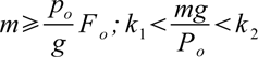
where
- m is the mass of the piles and of the vibratory pile driver (and of any additional loads)
- p0 is the required pressure on the pile, the value of which may be obtained from the data presented below
- F is the cross sectional area of the pile; Po is the maximum driving force of the vibration exciter
- k1 and k2 are coefficients
- for a steel sheet pile k1 = 0.15 and k2 = 0.5
- for light (wooden, tubular steel) piles k1 = 0.30 and k2 = 0.6
- for heavy (reinforced concrete) piles and wells k1 = 0.40 and k2 = 1.0.
For piles inserted into water-saturated sandy and slightly clayey soils, the following values are recommended for the required pressure p0 (MPa) :
- Small diameter steel tubes and other elements with cross sectional area up to 150 cm2 …… 0.15-0.3
- Wooden and tubular steel (with closed end) piles with cross sectional area up to 800 cm2. . . . 0.4-0.5
- Reinforced concrete piles with square or rectangular cross section up to 2,000 cm2. . . 0.6-0.8
After the main characteristics are obtained, the required power of the motors is determined:
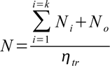
where
- htr is a coefficient indicating the energy losses in transmission from the motor to the shafts of the vibration exciter.
The power (in kw) spent on overcoming resistances in the vibration exciter mechanism is:

where
- d is the diameter of the journals on the shafts of the vibration exciter, in cm
- n0 is the rotational speed of the shaft, rpm
- f is the coefficient of friction of the rolling-contact bearings relative to the diameter of the shaft journal, approximately equal to 0.01.
The power (in kW) required to overcome the resistance of the ground is:
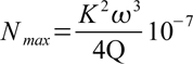
where
- K is the eccentric moment of the vibration exciter’s unbalanced masses
- w is the angular velocity of the vibration exciter’s unbalanced masses.
Since the derivation of the formula did not take into account energy losses to vibration of the ground, it is recommended that, in every case, the value of Nmax obtained by this formula be increased by 10 to 20 percent.


5 thoughts on “Vibratory Machines for Sinking Piles: Vibratory Pile Drivers”