

Yu. V. Dmitrevich, VNIIstroidormash
L.V. Erofeev, Stroifundamentservice
V.A. Nifontov, Stroifundamentservice
D.C. Warrington, Vulcan Iron Works Inc.
This article was originally published in 1993 or 1994. The graphic above shows a 9 kJ unit mounted on an excavator.
Introduction
Hydraulic demolition hammers mounted on hydraulically powered excavators are becoming increasingly widespread in world practice. They allow the excavators to be used for breaking rock and permafrost, break up large rocks, old foundations and reinforced concrete structures, and other jobs.
Outline of the Machine
Hydraulic demolition hammers are often equipped with hydraulic accumulators in the pressure line and sometimes in the drain line as well (as is the case with the Raymond hydraulic pile driving hammers) to achieve higher efficiency and to smooth pulses of fluid pressure in the hydraulics. Compressed nitrogen is mostly use as the elastic element in these accumulators.
The proposed hydraulic hammers differ from similar machines of leading companies outside of Russia such as Krupp of Germany, Montaber of France, and NTK in Japan. The main difference is in the accumulators the Russian machines have no compressed nitrogen accumulators, but are equipped with hydraulic accumulators having a so-called “liquid spring,” which is a closed volume of hydraulic oil compressed under pressure four or five times the pressure in the hydraulic system. Possible leaks from the inside of the hydraulic spring are compensated automatically when the hammer is switched off. Such a hydraulic accumulator does not need any adjustments and control during operation and its parts can serve as long as the hammer itself.
The main reason this design was chosen relates to the conditions in Russia itself. The temperature gets very cold, down to -60° C under these conditions the rubber in the bladder type gas accumulators will become embrittled in the temperatures common in many parts of Russia. Once this has happened, the bladders will burst and the machine will have to be completely disassembled and the bladder replaced. This operation is tedious enough on a normal construction site it is a greater problem when the job is somewhere above the Arctic Circle in Siberia.
Another specific feature of these hydraulic hammers is that their rams are not integral with the piston but are connected with the latter through a special elastic hinge. All the hydraulics of the hammer are centralized into a separate unit comprising the working cylinder, distribution valve and hydraulic accumulator. The ram can be of any size as required. The weight of the ram is selected so as to provide the impact energy at an impact velocity of no more than 6 m/sec. The weight of the ram is generally double that the the impact tool with other machines, it can be only half. This provides a high impact efficiency and increases the efficiency of the hydraulic hammer as a whole.
The power output of an impact hammer is the product of the impact energy of the hammer and the number of blows per minute. Thus, for the same power output an impact hammer can have either a high number of blows per minute and a low rated striking energy or a low number of blows per minute and a high impact energy. The advantage of the latter condition, however, is that the higher impact energy can be decisive in producing the high impact force levels necessary to demolish the work at hand. This is why these units have demonstrated outputs two or three times as high as those produce by Kone (Finland,), Krupp (Germany,) and have also outperformed those from Ingersoll-Rand.
The efficiency of these hammers is further promoted in breaking permafrost and rocks by the streamlined shape of the tool itself, which permits the operator to sink the whole hammer into the medium to a greater depth than just the length of the impact tool, i.e. a deeper layer than can be broken at one pass. Thus, there is no need to make the tool very long and the hammer can be operated as a lever, tearing large pieces away from the permafrost or rock. Other companies prohibit such handling of their demolition hammers. The strength of the tool and of the hammer body permit such operation in the case of the Russian machines.
Table 1 shows the standard sizes of the hydraulic demolition hammers based on these principles.
Table 1 Specifications for Hydraulic Demolition Hammers
| Specification |
Size I |
Size II |
Size III |
Size IV |
Size V |
| Impact Energy, kJ |
1.8 |
3 |
6 |
9 |
20 |
| Blows per Minute |
300 |
180 |
240 |
160 |
125 |
| Hammer Weight, kg. |
450 |
840 |
1500 |
2100 |
3700 |
| Ram Weight, kg. |
100 |
200 |
400 |
600 |
1000 |
| Weight of Impact Tool, kg |
50 |
100 |
200 |
300 |
|
| Insertion Diameter for Impact Tool, mm |
100 |
135 |
150 |
180 |
|
| Hydraulic Oil Consumption, l/min |
120 |
120 |
165 |
165 |
200 |
| Working Pressure, MPa |
16 |
16 |
16 |
16 |
20 |
| Connecting Hose Size, mm |
20 |
20 |
25 |
25 |
|
| Weight of base excavator, metric tons |
6-12 |
10-20 |
18-25 |
20-36 |
30-45 |
| Maximum depth of loosening of permafrost or rock per pass, mm |
600 |
800 |
1000 |
1200 |
The Size I has been produced in Belarus since 1982 and the Size IV in Russia since 1978. Sizes II and III have been tested as prototypes and are proving to be the most popular sizes. The design of the hammer is patented in Germany, Hungary and Finland.
Hydraulic hammers of Sizes IV and V may be used for driving small piles after some modification.
Description of Design
The hydraulic demolition hammer is mounted onto excavators as an interchangeable tool by means of an intermediate bracket which is secured both to the excavator and to the hydraulic hammer
Figure 1 shows the main parts which constitute the structure of the demolition hammer. The working cylinder (Figure 2) is essentially a body having a heat treated steel sleeve inserted therein, the latter accommodating a piston moving therein. The body of the work cylinder accommodates a check valve and a hydraulic accumulator comprising a piston with a head and rod, a bushing and a fluid spring enclosed in the cavities bored into the body and communicated with each other and with the rod end of the accumulator by means of ports.


As shown in Figure 3, a plug is provided to let air out from the cavity of the fluid spring when the latter is being filled with the working fluid.
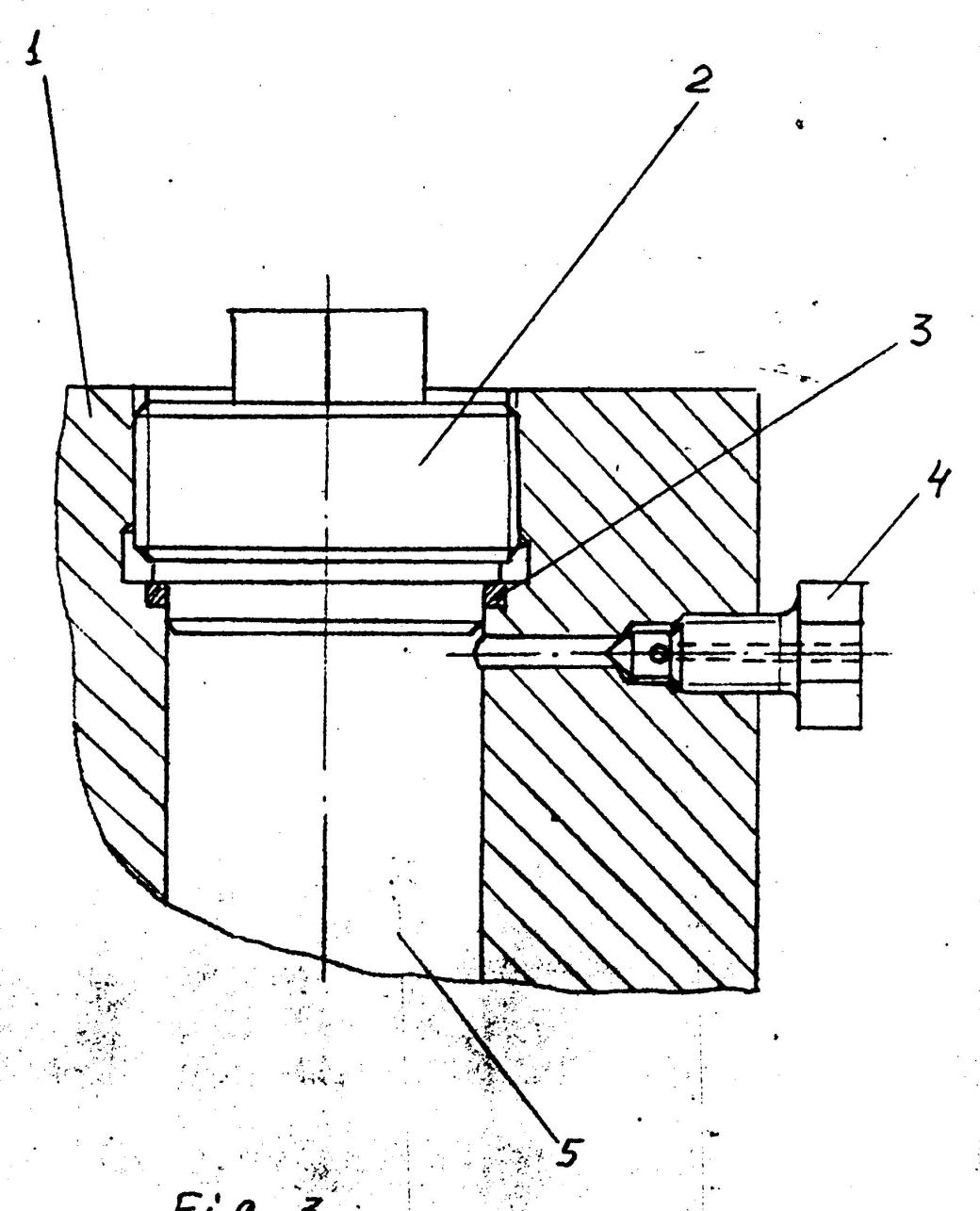
The rod of the hydraulic accumulator is spring loaded. The head end of the accumulator is communicated with the fluid spring through a check valve intended to compensate for leaks from the cavities of the fluid spring when the hydraulic hammer is switched one and off. The work cylinder is closed from the top with a lid.
The impact portion of the hydraulic hammer is suspended from the rod of a piston by means of rubber shock absorbers. These decrease the dynamic loads acting on the rod. The impact portion moves in the guide pipe. Ports are provided in the upper and lower portions of the guide pipe and these intercommunicated by air ducts. With the impact portion moving, air flows freely from one cavity into the other one through the air ducts.
The impact portion delivers by its lower end blows upon the tool, which can move freely downwards for 60 mm along the guide of the axle box mounted on the guide pipe.
Principle of Operation
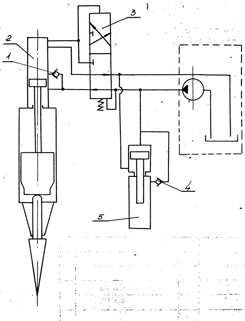
Looking at Figure 4, the ram, rod and piston are in their initial position, which is resting on the impact tool. The control valve occupies the upper position under the action of a spring mounted under its lower end position. This communicates the rod end of the work cylinder with the pressure line. It also communicates the head end with the drain line of the hydraulic system, the piston of the hydraulic accumulator occupying the upper position.


After the pump is started, the working fluid gets through the valve into the rod end of the working cylinder and the space above the piston of the hydraulic accumulator. As a result of this the impact portion starts accelerating upwards. This forces the fluid from the head end of the working cylinder through the port along the drain line into the tank, whereas the piston of the hydraulic accumulator moves downwards.
Moving on to Figure 5, at the end of the upward acceleration, the piston passes the drain port, as a result of which pressure in the head end of the working cylinder, the duct and above the upper end of the valve rises. Since the area of the upper end of the valve is greater than that of the lower one, the valve moves into the lower position, thereby communicating the head end with the pressure line and the rod end with the drain line.
This is followed by the phase of slowing the ram to a stop in the upstroke, whereby the piston forces the fluid from the head end into the hydraulic accumulator.
After the ram has stopped at the top of the stroke, it starts accelerating downward under both the force of gravity and the fluid pressure on the head end of the piston. After the impact portion has acquired a speed where it outruns the hydraulic pump, the hydraulic accumulator starts to discharge, and its piston moves upwards. At the end of the downward stroke the ram strikes the impact tool, which moves relative to the body of the hammer so the tool can penetrate the soil. Before the blow is delivered, the upper edge of the piston lowers below the check valve, whereby the head end is communicated with the drain line. As a result of this, the pressure in the head end and above the upper edge of the control valve drops down to a value at which point the spring mounted under the control valve can move the control valve upwards.
After this, the cycle can be repeated. Figure 6 shows the hydraulic schematic for the system.
Additional Features
The fluid spring is used in the structure of the accumulator. In this spring the pressure exceeds that in the hydraulic system by as many times as the area of the piston exceeds the area of the rod entering the cavity of the fluid spring.
Possible leaks from the cavity are compensated by the hydraulic system after the pump through the check valve, with the piston being displaced by the spring mounted thereunder.
The hydraulic hammer cannot be started unless it is applied against the work. Without the work being applied against the impact tool, the block head occupies the lowest position and the upper surface of the piston is lowered below the ports through which the fluid gets into the rod end. An attempt to start up the hammer without the hammer applied against the work results in the fluid passing freely over into the tank, and the hammer does not operate.
Conclusion
The hydraulic demolition hammer with fluid accumulator has proven itself both in theory and in practice. It has as rugged and simple design and is capable of performing many kinds of work. It overcomes many of the difficulties of other designs without unacceptable compromises in performance.

