
For more of this book, click here.
If water-bearing formations consist of sands, it is advisable to install wire-wound filters with a gravel pack in the wells. This pack improves the filtration characteristics of the zone around the filter. It also increases well productivity and stabilizes its operation as a water source.
One of the most rational design methods for this type of intake part of a well in percussion-cable drilling consists of using wire-wound filters on a tubular frame. The lower end of this frame is equipped with a conical shoe-reamer.
The advantage of installing filter columns with a conical shoe-reamer, compared to the conventional technology of constructing wells with percussion-cable rigs, is that it eliminates the need to lower an intermediate column of casing pipes into the well and subsequently pull it out to expose the filter.
When using a conical shoe-reamer, drilling (excavation of soil by a bailer) is performed simultaneously with lowering the filter column pipes and backfilling a gravel-sand mixture into the annular space between this pipe and the production casing. To lower the filter column, a specially mounted pulley system is typically used, which presses down the pipes with a force up to 100 kN.
The disadvantage of this installation method is that the pulley system partially blocks the wellhead and complicates work with the bailer. Furthermore, during penetration through dense soil layers, it does not provide the required speed of filter installation, which in several cases leads to accidents associated with column seizing.
These disadvantages are eliminated if vibratory machines with a central through-hole are used for lowering the filter column, allowing simultaneous operation of the vibrator and the bailer. Vibratory action, besides significantly accelerating the column installation process, improves the conditions for forming the gravel pack. It reduces gravel segregation during backfilling, eliminates the possibility of it getting hung up, and expands the contour of the gravel pack. This, in turn, increases not only productivity but also the quality of the constructed water supply wells, as repeatedly confirmed by industrial experience.
Among the existing vibratory machines (see Table 14) that have a through-hole, the VO-10 vibrator and S-835 impact-vibration hammer can be used for installing filter columns with a conical shoe-reamer. These machines are designed for installing and extracting casing pipes with a diameter of 168–273 mm.
Existing experience using the VO-10 vibrator for installing and extracting casing pipes has shown that it has low reliability. This is due to the design imperfection of its clamping device, which requires significant time for auxiliary operations.
Regarding the S-835 impact-vibration hammer, its use for installing filter columns is not rational. This is because the impact-vibratory action, due to the significant magnitude of accelerations imparted to the installed element, leads to the disruption of the winding pitch of the wire coatings of the filter.
Analysis (V. B. Verstov, L. L. Libin, 1978) showed that a vibrating machine for driving filter strings with conical shoe-expanders during the construction of water wells with percussion-cable rigs using gravel-wire filters must meet the following requirements:
- Ensure during drilling the immersion of filter pipes with a diameter up to 426 mm and a length up to 100 m in a vibration mode (such dynamic action is rational for structural elements of the filter and effective in water-saturated sands both for overcoming the resistance forces to pipe immersion and for the power consumed by the vibrator);
- Possess a through-hole with a diameter up to 350 mm for passing the bailer;
- Have a fast-acting driving head with a through-hole;
- Allow, in addition to the main purpose, performing work on the immersion and extraction of casing pipes during the construction of wells on water to a depth of up to 60 m.
Taking into account the above, VNIIGS developed, and the “Promburvod” trust mastered the production and implemented two standard sizes of specialized specialized vibrators: VPF-1 and VPF-2 (see Table 14), which can submerge filter strings with conical shoe-expanders of all diameters used in the practice of drilling operations.
The ultimate depth of immersion using VPF-1 filter strings with a diameter of 273 mm is 60 m, and VPF-2 with a diameter of 325 mm is 100 m. Casing pipes with a diameter of 168–325 mm VPF-1 can submerge during the construction of wells on water to a depth of up to 40 m, and VPF-2 with a diameter of 219–426 mm — to a depth of up to 60 m.
Vibrators VPF-1 and VPF-2 are identical in design and differ only in static eccentric moments and power of drive electric motors. The vibrators consist of a two-shaft eccentric vibration exciter, two electric drive motors of standard design, installed on the top plate of the vibration exciter housing, and a driving head. In addition, the kit of each vibrator includes a spring shock absorber, an electric control panel, and adapters for pipes of different diameters. The vibration exciter is located in a welded housing, in the center of which there is a through-hole with a guiding socket in the upper part.
The driving head is made in the form of a wedge clamp, built according to the scheme of Fig. 32, in which jamming of two parts is performed by turning levers with eccentric bushings using the tackle system of the drilling rig. Schemes of operation of vibrators of the VPF type during immersion and extraction of pipes are shown in Fig. 98.
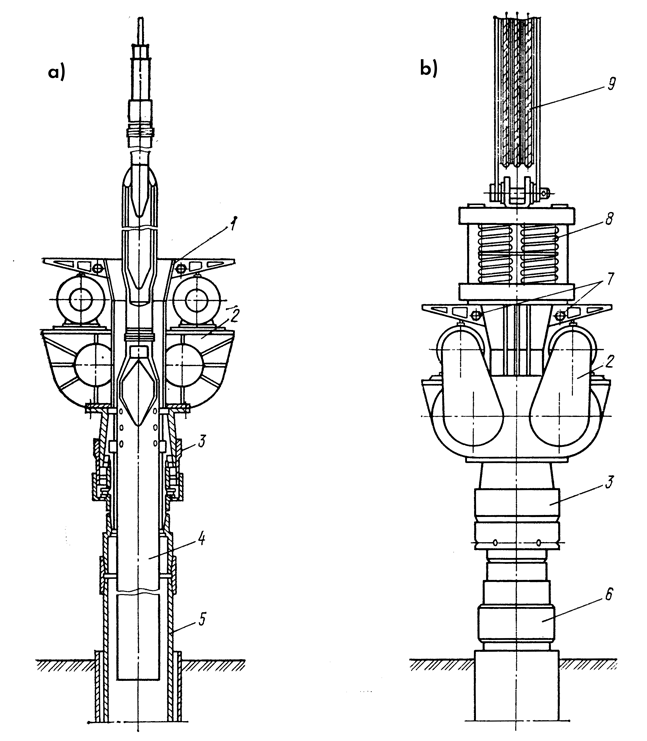
1 – socket of the vibrator exciter housing;
2 – vibration exciter;
3 – driving head;
4 – bailer;
5 – submerged pipe;
6 – extracted pipe;
7 – spring shock absorber attachment pins;
8 – spring shock absorber;
9 – lower block of the drilling rig tackle system.
Fig. 99 presents the technological scheme of installation of a gravel-wire filter with the use of a VPF-type vibrator for driving a filter string of pipes with a conical shoe-expander. In such cases, the conical shoe-expander is screwed onto the first pipe of the filter string and the string is lowered into the pre-cased upper boundary of the water-bearing horizon of the well (the diameter of the production casing string must be larger than the diameter of the filter string by at least 100 mm). Then, the drive head is attached to the coupling of the last pipe of the filter string, and the vibrator is mounted. The filter string is lowered by periodically turning on the vibrator while simultaneously cleaning the bottom of the borehole with a bailer and pouring the gravel-sand mixture into the space between the production casing and the filter pipe string. During the vibro-sinking of the filter, the level of the gravel-sand mixture must be maintained 2–3 m above the shoe of the production casing by continuous backfilling.
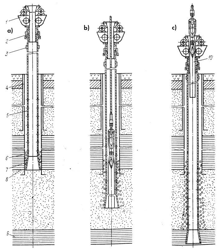
a, b, c — initial, intermediate, and final stages respectively; 1 — vibrator; 2 — drive head; 3 — filter pipe coupling; 4 — production casing; 5 — filter string; 6 — gravel-sand mixture; 7 — tapered shoe-expander; 8 — upper boundary of the aquifer; 9 — impermeable rock (aquiclude); 10 — bailer
Fig. 100 shows structural diagrams and geological profiles of some of the most typical water wells constructed using UGB-3UK (UKS-22) cable-tool drilling rigs and the VPF-1 vibrator. In all wells, a vibratory technology was used for setting the filter strings with a tapered shoe-expander and sinking the casing pipes. In several cases, after the completion of well construction work, the intermediate strings were extracted using vibration (these strings are shown with dashed lines in the figure).
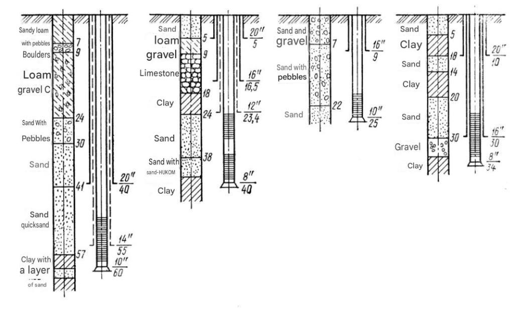
(Note: Casing pipe diameters are indicated in inches, e.g., 20″, 16″, 14″, 12″, 10″, 8″)
Table 20 contains comparative data on the use of the VPF-2 vibrator (Fig. 101) and the driving tool of a drilling rig for sinking and extracting casing pipes with a diameter of 273–426 mm during the cable-tool drilling of water wells in sandy-clayey soils containing gravel and small boulders.
Figure 101. General view of the VPF-2 vibrator during the sinking of a 426 mm diameter casing pipe.
Accumulated experience in using VPF-type vibrators during cable-tool drilling of water wells under various hydrogeological conditions allowed for the following conclusions. The vibratory technology of setting filter strings with a tapered shoe-expander, combined with simultaneous drilling of the well and gravel backfilling, ensures a high penetration rate and allows effective sinking of the filter through dense clay interlayers encountered in water-bearing sandstone. This reliably ensures the placement of the filter into the water-bearing stratum along its entire working length, with the shoe-reamer embedded into the aquitard (confining bed).
Table 20. Comparison of the results of using the VPF-2 vibrator and the driving tool of a drilling rig for sinking casing pipes
| Well No. | Interval, m (Sinking) | Interval, m (Extraction) | Brief Description of Rocks and Soils | Yield of Sludge, m | Sinking Speed: VPF-2 (m/min) | Sinking Speed: Driving Tool (m/min) | Extraction Speed: VPF-2 (m/min) | Extraction Speed: Driving Tool (m/min) |
|---|---|---|---|---|---|---|---|---|
| 1 | 40–50 | — | Dense loam | 3.0 | 4.0 | 1.5 | — | — |
| 2.5 | 1.0 | 0.5 | — | — | ||||
| 50–60 | — | Dense loam | 0.5 | 0.5 | 0.2 | — | — | |
| Dense clay | 3.0 | 1.5 | 0.8 | — | — | |||
| — | 70–80 | Loam with boulders | — | — | — | 1.5 | 0* | |
| 2.5 | 1.2 | 0.7 | — | — | ||||
| 2 | 50–60 | — | Coarse sand with gravel | 1.0 | 2.4 | 1.0 | — | — |
| — | 70–80 | Dense clay | — | — | — | 1.0 | 0* | |
| 3 | 50–60 | — | Dense loam | 0.5 | 0.6 | 0.2 | — | — |
| — | 60–70 | Fine-grained silty sand with clay interlayers | — | — | — | 1.5 | 0* | |
| 4 | 40–56 | — | Loam with boulders | 2.0 | 1.5 | 0.8 | — | — |
| 0.5 | 0.5 | 0.2 | — | — | ||||
| 5 | 40–50 | — | Loam with boulders | 2.0 | 1.5 | 0.7 | — | — |
| 0.8 | 0.7 | 0.3 | — | — | ||||
| 50–60 | — | Fractured, weakly cemented sandstone | 1.0 | 0.3 | 0.1 | — | — | |
| 6 | 40–50 | — | Dense loam with boulders | 1.5 | 1.2 | 0.4 | — | — |
| 1.0 | 1.0 | 0.3 | — | — | ||||
| 50–62 | — | Dense loam with boulders | 1.5 | 1.1 | 0.4 | — | — | |
| Fractured, weakly cemented sandstone | 1.0 | 0.4 | 0.15 | — | — |
*During work with the driving tool, upward movement of pipes during their extraction did not occur.
In water-saturated sandy strata, without cleaning the borehole with a bailer, a vibro-driven casing string using these vibrators can achieve a speed of about 1 m/min for stretches of 8–10 meters. On average, the vibrational installation of a filter string with a diameter of 273–325 mm equipped with a conical shoe-reamer takes 1–1.5 working shifts. This timeframe includes all other secondary operations required to construct the water-intake section of a gravel-wire filter.
During this process, the operational parameters of the vibrators are characterized by the following data:
- Angular velocity of the eccentric shafts is 800 RPM.
- Vibration amplitude ranges from 6–8 mm at the initial stages of sinking down to 2–3 mm at the final stages, depending on the mass of the filter string and soil resistance.
- Required power for the VPF-1 drive is 10–15 kW at the initial stages and up to 20 kW at the final stages.
- Extraction power requires 20–25 kW and up to 30 kW, respectively.
The operational experience of drilling operations showed that to effectively overcome dense clay layers encountered in the water-bearing stratum using a vibrating filter pipe with a shoe-reamer. The presence of clay layers facilitates operations at the bottom hole instead of using a conventional bailer or drilling tool made from a BC-1 impact-vibratory tool and a flap-type core lifter.
The weight, dimensions, and vibration parameters of the VPF-1 vibrator allow it to be used for drilling water wells at depths of up to 20 meters. This is done in combination with light, self-propelled ABO-1 units equipped with a friction winch and a bailer. These are designed to perform well development and repair operations, bypassing the use of complex, heavy percussion drilling rigs.
In an existing project, wells were constructed by vibratory sinking from the ground surface of a filter column made of 219 mm diameter pipes. This featured a conical shoe-expander reaching a depth of 16 meters, while simultaneously backfilling gravel into the annular space. The full cycle of constructing such a well using vibratory technology takes 3 working shifts. This minimizes time spent on preparatory operations and equipment transportation, reducing labor costs by more than 50% compared to percussion-cable drilling.
An analysis of the results of using VPF-type vibrators for sinking casing pipes showed that, compared to driving them with the drilling rig’s impact tool, they more than double the speed of pipe placement and increase their extraction rate by 20–30%. The VPF-1 and VPF-2 vibrators provide vibratory extraction of intermediate casing strings from wells in cases where using an impact tool yields no positive results.
During the vibratory sinking of casing pipes in cohesive soils with simultaneous bailing of the bottom hole, the power required to drive the vibrator reaches up to 30 kW for the VPF-1 and 50 kW for the VPF-2. When vibrator-extracting intermediate pipe strings with a static pull of 140–160 kN at the moment of pipe breakaway relative to the soil, the amplitude of vibrations for both vibrators is 2–3 mm. The required drive power for the VPF-1 falls within 10–12 kW for a pipe string length of up to 60 meters.
Experience has shown that using conventional, standard electric drive motors on vibrators ensures sufficient durability. This is due to the relatively low vibration amplitudes, the impossibility of the vibratory system entering an impact-vibration operating mode, and the relatively small masses of the electric motor stators.
The use of vibratory technology to install gravel-packed filter structures with a conical shoe-expander safely permits the progressive design of the water-receiving part of a water well. This eliminates the risk of emergencies associated with sticking filter pipes during installation during percussion-cable drilling. It also increases work speed by 10–15%.


One thought on “Installation Of Filter Columns When Constructing Gravel-Packed Wire-Wound Filters In Water Wells”