
For more of this book, click here.
In the process of percussion-cable drilling, bore hole walls are reinforced with casing pipes to prevent collapse and to isolate water-bearing horizons.
The low driving capacity of a drilling tool and the lack of reliable means for extracting intermediate columns when filters are exposed lead to a situation where, in percussion-cable drilling, the extension of casing columns into the formation does not exceed 30–40 m. When driving large-diameter pipes (426–630 mm), the extension is even smaller—within the range of 20–30 m.
The small extension of casing columns into the formation necessitates the use of multi-column designs when constructing boreholes with a depth of 100–150 m, which increases pipe consumption and delays production schedules.
At the end of the 1950s, following experimental work on vibro-driving with vibratory drivers by the NIIOSP institute, and also on the driving and extraction of casing pipes using VNIIGS vibratory drivers type VPP-2 and VPP-4, along with vibrators and impact-vibration hammers of various designs began to be used in percussion-cable drilling.
Table 14 shows the technical characteristics of vibratory drivers developed in our country, designed for the driving and extraction of casing pipes. As a result of work carried out by several organizations—Minmontazhspetsstroy USSR, Mingeo USSR, Minenergo USSR, Minvodkhoz USSR with B-108, VO-10 vibrators and S-835 impact-vibration hammers—it has been established that the use of vibration machines in percussion-cable drilling makes it possible to:
- Increase the extension of casing columns into the formation;
- Perform leading casing of borehole walls when drilling water-saturated soils;
- Carry out the extraction of intermediate columns during filter exposure when extending into formations up to 30–40 m with relatively small static forces (200–250 kN).
However, vibratory drivers of these types have not received widespread distribution in percussion-cable borehole drilling practice. Analysis showed that the increased pipe-driving speed provided by these mechanisms does not compensate for the significant amount of time spent on auxiliary operations, and therefore labor productivity remains low. The main disadvantage is the need for a rigid connection between the vibro-mechanism and the casing pipe. This operation requires significant time and is labor-intensive and unsafe, as it is performed at a considerable height (when securing the vibrator to a newly driven pipe; and when removing the vibrator from an extracted column).
Furthermore, the productivity of drilling operations decreases due to frequent removals of the vibro-mechanism from the casing pipe to clean the borehole with a bailer. This is because, due to insufficient soil-driving capacity, advancing the pipe through the entire free height in a single setup is often impossible.
Based on this analysis, M.G. Tseitlin, V.V. Verstov, and L.A. Libman (1968) concluded that a vibro-mechanism for driving and extracting casing pipes during percussion-cable drilling must meet the specific features of drilling operations and satisfy the following conditions:
- The driving and extracting capacity must be high in both soft and dense formations;
- The operating mode must create conditions for soil to pass into the internal cavity of the pipe to ensure a minimal number of transitions from pipe-driving to cleaning the borehole bottom with a bailer;
- The clamping device must be simple and universal, allowing operation with pipes of the required diameter (273–630 mm), minimizing time spent on auxiliary operations, and eliminating work performed at height.
To pick a rational type of such a vibro-mechanism, VNIIGS conducted an experimental investigation. Its objectives were to study the effectiveness of vibrational and percussion-vibrational driving of pipes under various soil conditions, as well as to compare different vibration-percussion driving schemes.
The efficiency of vibrational and percussion-vibrational driving was compared based on primary indicators: driving capacity (depth and speed of driving), the height of the formed soil plug, and power consumption.
A comparison of vibrational and percussion-vibrational modes showed that:
- When driving into water-saturated sandy loam at identical driving speeds, the power required in the vibrational mode is 1.5–2 times less than in the percussion-vibrational mode;
- When driving into low-plasticity loams and sandy loams, the driving capacity of impact-vibration hammers is higher than that of vibrators; for driving to an identical depth in the vibrational mode, the required power is 1.5–2 times greater than in the percussion-vibrational mode;
- The advancement of soil into the internal cavity of the casing pipe during percussion-vibrational driving occurs more intensively than during vibrational driving (Fig. 92).
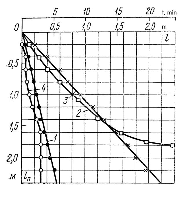
1, 2 — hodographs corresponding to impact-vibratory driving and vibratory driving, respectively;
3, 4 — movement of the soil plug during impact-vibratory and vibratory driving, respectively.
When comparing different configurations of impact-vibratory driving, it has been established that:
- The driving capacity of a free spring impact-vibration hammer is higher than that of a springless one, and its range of stable operation is significantly wider;
- The driving capacity of a spring impact-vibration hammer rigidly secured to the element being driven is somewhat higher than that of a free spring impact-vibration hammer.
It should be noted that during percussion-cable drilling of wells, casing pipes become significantly jammed in the rock; therefore, there is a fundamental difference in the operation of a spring hammer mounted on a pipe versus a free spring hammer. However, with a sufficiently high driving capacity, the free spring hammer offers operational advantages because it does not require rigid attachment to the driven element. Taking into account that the majority of the retrieved intermediate casing string is located in water-saturated sand when filters are exposed, it is highly practical to extract it in a vibratory mode.
In connection with this, VNIIGS and the “Promburvod” trust proposed, developed, and introduced into practice the BVS-1 free spring impact-vibration hammer for well drilling (see Table 14). The distinction of the BVS-1 impact-vibration hammer (Fig. 93) from vibratory hammers of a similar purpose lies in the fact that it does not require rigid attachment to the driven pipe and, at the same time, possesses a high driving capacity due to the effective utilization of the impact-static force pressing down on the casing pipe during the driving process via spring tensioning.

1 — drilling rig mast; 2 — bottom plate; 3 — driving head; 4 — impact cup; 5 — driven pipes; 6 — traction winch; 7 — rope tension limiter; 8 — equalizing block; 9 — tension block; 10 — control panel; 11 — cable; 12 — impact-vibration hammer.
Cables are used to tension the springs of the impact-vibration hammer; these run through tension blocks mounted on the conductor column to a separate traction winch or to the winch of the drilling rig.
The structural design of the impact-vibration hammer allows for quick reconfiguration of its operation from an impact-vibratory driving mode to a vibratory extraction mode for pulling casing pipes. For this purpose, the impact-vibration hammer is equipped with a removable wedge clamp, which completely eliminates manual labor operations during the attachment and detachment of the vibratory mechanism from the pipe (see Fig. 52, b). To prevent the harmful impact of vibrations on the mast of the drilling rig, a separate spring shock absorber is utilized. The parameters necessary for evaluating the efficiency of the operation were studied of a free-spring impact-vibration hammer when driving and extracting tubes.
It has been established that when sinking 273–630 mm diameter tubes with a BVS-1 type impact-vibration hammer during percussion-rotary drilling of a borehole under water through water-saturated fine sands and cohesive clayey rocks, a speed of 0.5–2.0 m/min is achieved. The height of the column’s extension into the rock is 50–60 m for the impact-vibration driving mode with spring tension, and about 20 m for the free-spring impact-vibration hammer mode. In a number of boreholes, tube sinking with spring tension was performed with step-by-step changes in the angular velocity of the eccentric shafts at a constant value of the static moment of the eccentric mass under identical sinking conditions.
The results of this work, presented in Table 19, show that the most rational mode is the one with a vibration frequency of 10 Hz. At a lower frequency, the sinking efficiency drops sharply, while at a higher frequency, the power required by the impact-vibration hammer drive reaches unacceptable levels for drilling operations.
| Vibration Frequency, Hz | Sin α | Power N, kW | Sinking Speed v, m/min |
|---|---|---|---|
| 8.3 | 0.6 | 25 | 0.1 |
| 10.0 | 0.7 | 40 | 0.7 |
| 11.7 | 0.65 | 75 | 0.9 |
An analysis of the operational results of the BVS-1 impact-vibration hammer set to a vibration frequency of 10 Hz revealed the following. During the process of sinking tubes into undisturbed ground in all rocks except dense ones, cleaning the bottom of the borehole with a bailer was required every 4–11 meters depending on the soil type; the power consumed by the impact-vibration hammer drive varied from 20 to 50 kW.
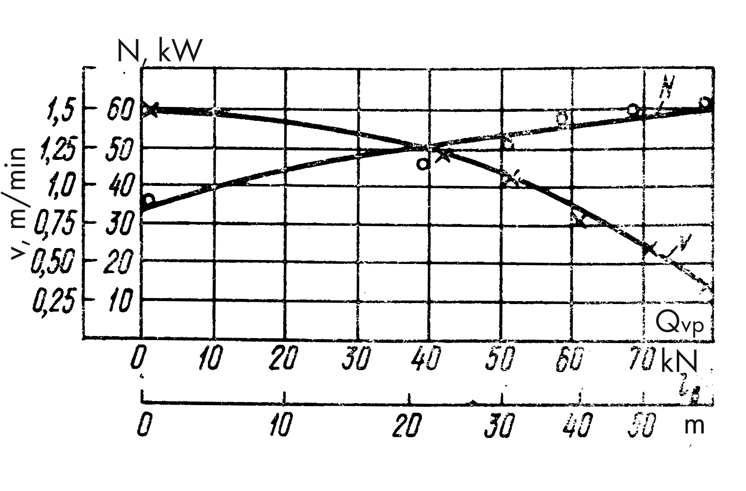
Figure 94 presents graphs characterizing the changes in sinking speed v and power N at a constant compression force of the working springs Qv.p depending on the height of the soil plug l in the intervals between bailer cleanings. As seen from the graphs, as the height of the plug increases, the tube sinking speed decreases significantly, and the power required to drive the impact-vibration hammer increases. Under these conditions, the impact-vibration hammer operated in the mode where 0.6 < sin α < 0.7.

As the tube was sunk down the open borehole (with preliminary bottom cleaning by a bailer), accompanied by an increase in the column’s extension into the rock, the tension force of the working springs was regulated from 0 to 80 kN (in the first stages of sinking, the impact-vibration hammer usually operated in the free-spring hammer mode), while 0.24 < sin α < 1.
Figure 95 shows graphs reflecting the relationship between the column sinking speed v and the power N consumed by the impact-vibration hammer, based on the column extension into the rock lv and the tension force of the working springs Qv.p for the case when the clamping force of the column is small. An analysis of the graphs shows that for this case, increasing the tension force of the working springs as the borehole deepens is a necessary condition for the effective installation of the string, and the driving process is accompanied by an increase in the power of the vibrator drive. We also note that adjusting the spring tension ensures stable operation of the vibrator in the “impact per revolution” mode over the entire length of the string.
The described pattern of driving a pipe into an open borehole changes in those cases when the clamping force of the string is in the range of the great (Fig. 96). Under these conditions, a springless vibrator, as well as a vibrator with a significant initial compression of the working springs, do not ensure effective driving of the pipe. At the same time, for the operation of a springless vibrator, the greatest amount of power consumption is required, and for the operation of a vibrator with a higher spring tension, the least. In this case, the most effective mode of operation of the vibrator was characterized by sin α = 0.8.

During vibro-extraction, a pipe string with a diameter of 219–426 mm was lifted from depths of up to 130 m with embedment in rocks of 30–40 m. In all cases, the extraction force did not exceed 170 kN, the extraction speed varied from 0.2 to 1.0 m/min, and the power required to drive the vibrator was 16–20 kW.
The driving of casing pipes by the BBS-1 vibrator (Fig. 97) is carried out in two modes at a vibration frequency of 10 Hz. The first mode of a free vibrator (without spring tension) should be used when driving conductor strings, and the second (main) mode with spring tension must be used when driving subsequent pipe strings.
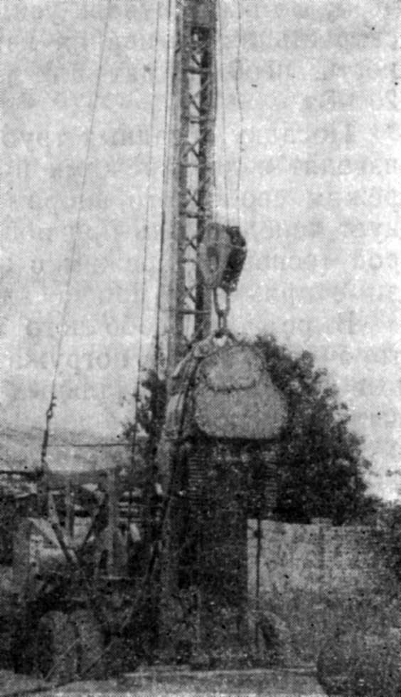
In the free vibrator mode, conductor strings must be driven to the full depth, and intermediate strings only in the initial period of their installation. In this mode, the embedment of the string in the rocks, as a rule, is 20–25 m, and the height of the soil plug in the pipe cavity does not exceed 4–5 m.
When operating as a free vibrator, the borehole should be cleaned only after the driving speed drops to 5–10 cm/min, and the vibrator operation mode is characterized by the absence of periodic impacts and significant swinging in the horizontal plane.
The vibrator operation mode with the tension of the working springs must be used for driving intermediate strings after the operation of the free vibrator ceases to be effective due to increased resistance to driving, i.e., when, after another cleaning of the borehole, the pipe driving speed does not change. With the tension of the working springs, the vibrator ensures the embedment of the string into rocks up to 60 m and allows driving pipes into water-saturated soils for 10–12 m without cleaning.
In the mode with spring tension, the driving speed of the pipe by the vibrator, as a rule, is within 0.2–1.0 m/min and is determined by geological conditions, the length of the string, and the amount of its penetration.
During extraction, the vibrator is rigidly fastened to the casing pipe by means of a self-locking gripper. In connection with this, since the extraction of casing pipes is carried out in a vibrational mode, the efficiency of which strongly depends on the frequency of vibrations, the design of the vibrator provides for the possibility of switching from a frequency of 10 Hz (the main one for impact-vibrational driving of pipes) to 11.7 and 13.3 Hz. For successful vibro-extraction of the string, the amplitude of pipe vibrations in the initial period of its lifting should be at least 4–5 mm.
The experience of introducing free spring vibrators BBS-1 in the trusts “Promburvod” and “Soyuzshakhtoosushenie” showed that these vibrators meet the technological requirements of drilling operations and ensure effective impact-vibrational driving and vibrational extraction of casing pipes with a diameter of 273–630 mm when constructing wells for water up to 130 m deep and technical single-string wells up to 30 m deep by impact-hammer rigs.
In comparison with the standard bailer tool of a drilling rig, BBS-1 vibrators allow:
- Increasing the pipe driving speed by 2 times or more;
- Increasing the embedment depth into rocks by 30%;
- Reducing the number of switches from bailing to pipe driving by an average of 3 times;
- Reducing the amount of effort required to extract pipes, and increasing the lifting speed by 2–4 times;
- Preserving undamaged the upper edge of threadless pipes with a diameter of 529 and 630 mm, which eliminates loss of metal and operations for cutting and leveling the end.
In comparison with other vibro-mechanisms of similar purpose, the use of BBS-1 vibrators with higher efficiency requires minimal time spent on auxiliary operations: installing the vibrator onto the driven (extracted) pipe takes no more than 5 minutes, and removing the vibrator from the driven (extracted) pipe takes about 5–7 minutes.
It should be noted that when working with a vibrator, all round-trip operations are performed using the instrument winch of the rig, and the tension of the vibrator during its installation on the wellhead is performed by a bailing winch or lines of the tension system. Fastening the pulling winch and assembling the tension system are carried out at each well only once and take no more than 4 hours, which are then compensated for by the productive work of the vibrator.
Thanks to the use of BBS-1 vibrators, a significant reduction in the consumption of casing pipes is achieved. On a number of instances using these impact-vibration hammers, operators successfully altered the projected design of the wells. They reduced the number of intermediate casing strings and significantly accelerated the production workflow.
The “Promburvod” Trust also utilized BBS-1 impact-vibration hammers on several emergency wells deeper than 100 meters. This was done to expose filters by pulling up heavily seized intermediate casing strings with diameters of 219 mm and 273 mm that had been sitting in water-bearing sands for several months. It is well known that under such conditions, it is critical to achieve the initial displacement—breaking the column free.
Operations demonstrated that the BBS-1 impact-vibration hammer, when tuned to a vibrational mode, can successfully perform this task if the lowering and extraction of the columns are initially alternated. To reduce the time spent “working” the pipes, it is advisable to press down on the column using a tensioning system during its vibrational immersion.
It should be noted that the intermediate strings extracted from these wells had significant un-wedged lengths in the ground (60–100 m) with a relatively small diameter (219, 273 mm). It turned out that pulling such pipes in an impact-vibratory mode is impossible. This is because the impact action on the upper end of a long, wedged pipe caused an elastic bouncing of the column, which led to a sharp increase in energy consumption by the impact-vibration hammer but yielded no positive results.
Because of this, it is crucial that in such cases, the impact-vibration hammer can be reconfigured from an impact-vibratory mode to a static vibration-driving mode.
A techno-economic analysis shows that using BBS-1 impact-vibration hammers during percussion-cable drilling can significantly increase labor productivity. An UGB-ZUK (UKS-22) rig equipped with standard cable tools can sink five to six wells a year to a depth of 100 meters. However, when using the BBS-1 impact-vibration hammer, this indicator can be increased up to eighty percent.


One thought on “Immersion And Extraction Of Casing Pipes In The Process Of Percussion-Cable Drilling Of Boreholes”