
For more of this book, click here.
During impact-cable drilling, the destruction of hard and cohesive soils by existing drilling tools occurs through periodic impacts of the rock-breaking tool on the bottom of the well. Due to the low efficiency of such action, it requires significant time and cost. It is established that the rock-breaking capability of a drilling tool for impact-cable drilling can be increased by utilizing high-intensity dynamic action on the bottom during its contact with the rock.
It is known that the resistance of hard rocks to shear and tensile deformations is nearly 10 times less than under compression, and their dynamic hardness is several times less than their static hardness. Considering the process of cable-tool drilling from this point of view, where rock destruction occurs during periodic impacts of the wedge-shaped blade of the drill bit against the bottom of the borehole, it can be concluded that by the nature of the forces acting on the rock, it is the least rational method.
In this case, the low speed of cable-tool drilling in hard rocks is explained by the insufficient frequency of dynamic loading on the bottom of the hole (existing equipment does not allow a strike frequency of more than 50 blows per minute) and the fact that the impact energy of the drill bit is used inefficiently. The design of current drilling tools only ensures a small displacement of the bit into the rock, where only 20–30% of the impact energy is spent on shearing/chipping, while the rest is wasted on compression.
From the above, it follows that without increasing the mass of the drilling tool and its dimensions, the speed of cable-tool drilling in hard rocks can be increased by increasing the frequency of the drill bit strikes against the borehole bottom.
Drilling tools developed by VNIIBT [25] are capable of generating and transmitting additional dynamic loads to the bit within a single operating cycle, in addition to the main impact. These additional loads manifest fatigue properties in the rock, helping to reduce the time required for its destruction.

1 — cable lock; 2 — springs; 3 — upper limiter; 4 — housing; 5 — striker; 6 — lower limiter; 7 — drill bit.
Such a drilling tool (Fig. 81), like a conventional one, consists of a rock-destroying drill bit, an impact stem, and a cable lock. In contrast to existing drilling tools, the impact stem in this design is made in the form of a sealed housing, inside of which a striker is mounted using springs. Anvils are mounted on the lower and upper ends of the striker inside the housing, and anvils are also installed in the bases of the housing. The stiffness of the springs is selected such that in the idle position, there is a clearance between the striking pieces and the anvils.
During the drilling process, as a result of the main strike of the drill bit against the bottom of the borehole, the impact stem enters an oscillating state. During the period when the drill bit is in contact with the rock, the striker strikes a series of oppositely directed blows against the anvils. This impact-vibration behavior of the tool assembly helps intensify rock destruction and eliminates the possibility of the drill bit jamming at the bottom of the hole.
As can be seen, the design solution underlying the tool layout involves the use of a two-mass system. When this system is taken out of its equilibrium state during the downward release of the tool, the spring-loaded striker undergoes oscillatory movements relative to the housing. Upon interaction of the rock-destroying drill bit with the borehole bottom, the tool begins to operate in an impact-vibratory mode, delivering successive blows to the lower and upper limiters of the housing. In this configuration, the concentric placement of the spring-loaded striker installed inside the tool housing with a guaranteed clearance relative to the walls eliminates any possibility of it dragging against the walls during oscillations. This reduces energy losses for driving the striker, while the absence of assemblies with moving elements operating directly in the drilling mud increases the operational reliability of the drilling tool.
Investigations (B. V. Verstov, B. M. Lukin, 1982) allowed for identifying the specific features of the interaction between the borehole bottom and the rock during destruction by the bit of a new type of drilling tool, choosing the optimal technological operating regimes, determining the rational field of application for the tool, and compiling a method for calculating its parameters.
Theoretical studies on the motion of the tool-sludge-rock system in a borehole have established that the penetration of the bit into the rock per single drop of the tool does not depend on the mass ratio of the striker and the body under a constant overall tool mass. The specified regularity is illustrated by Fig. 82, where γ characterizes the magnitude of the dimensionless penetration, and β represents the mass ratio. The maximum penetration in the case of an increased velocity recovery coefficient during the impact of a spring-loaded striker against the limiters occurs when the values of β shift toward larger values. For a conventional tool under comparable conditions of operations γ = 0.86, which is why using a strike-vibrational drilling tool is more effective than using a tool of a conventional design when β > 0.2.
As the unconfined compressive strength of the rock increases, it is noted that, proportional to the increase in rock hardness, the bit penetration per single tool drop decreases. The shape of the curve characterizing this regularity corresponds to the graph plotted for a strike-vibrational tool of a conventional design; however, the absolute penetration values for the strike-vibrational tool are higher.
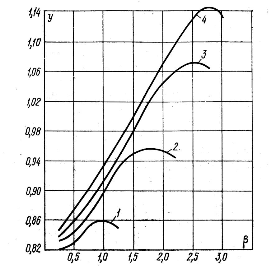
1 – R=0.2; 2 – R=0.3; 3 – R=0.4; 4 – R=0.5
Figure 83 shows a graph indicating the fields of technological parameters: sludge density ρ and tool drop height l, at which the bit penetrates the rock. Line A-A on the graph corresponds to the maximum value of penetration at various ρ and l. The points of curve B-B determine the values of ρ and l at which the impact interactions of the spring-loaded striker and the body end before the upward lift of the drilling tool by the rig mechanism begins. Line V-V corresponds to the values of ρ and l at which the lifting of the drilling tool begins earlier than the bit reaches the bottom of the borehole.
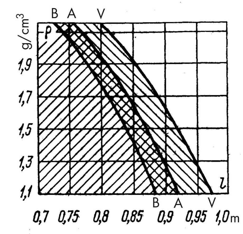
An analysis shows that the graphical zone bounded by curves A-A and B-B represents the field of tool operation with maximum bit penetration into the rock (the regime of highest productivity). The zone characterized by values of ρ and l lying to the left of line B-B corresponds to the operation of a drilling tool with reduced bit penetration into the rock. Moreover, finding a stationary bit that is not subjected to dynamic impacts at the borehole bottom can be accompanied by the occurrence of emergency situations associated with the sticking of the bit by the rock.
The operation of a strike-vibrational tool at values of ρ and l located in the zone bounded by curves A-A and V-V is characterized by a sharp reduction in bit penetration into the rock, because under such conditions the striker does not have enough time to transfer accumulated energy to the body during its downward drop. In this case, the impacts that the spring-loaded striker delivers against the body limiters after the tool is lifted above the borehole bottom cause overloads on the instrument cable, the striking mechanism, and the rig as a whole.
At values of ρ and l located to the right of line V-V, the lifting of the drilling tool begins before the bit reaches the borehole bottom, and the entire energy of the tool is wasted on creating overloads in the structural elements of the drilling rig.
Experimental laboratory studies were carried out with a model of a drilling tool, the design of which provided for adjustment to an operating mode with additional impacts, as well as to a conventional mode.
The studies were conducted on a test bench that simulates the operation of a cable-tool drilling rig. During the experiments, the forces in the body of the tool model during the interaction of the bit with the hole bottom, the movement of the bit (Fig. 84), and the volume of rock drilled per unit of time were recorded.
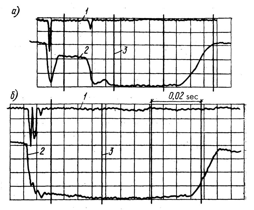
a — for a conventional drilling tool design; δ — for a strike-vibrational drilling tool; 1 — longitudinal forces in the tool model body; 2 — displacement of the bit relative to the rock; 3 — time marker.
Experimental studies confirmed the theoretical conclusions about the dependence of the bit penetration into the rock on the ratio of the mass of the impactor and the body of the tool, and showed that a decrease in this ratio leads to an increase in the specific work spent on the destruction of the hole bottom (Fig. 85). It was established experimentally that the minimum value of specific work Lud is achieved at a value of β = 1.6; in theoretical studies, the maximum penetration of the bit for a vibro-impact drilling tool with B = 0.3 was obtained for β = 1.75 (see Fig. 82).
Fig. 85. Dependence of the specific work expended on rock destruction at the borehole bottom on the mass ratio of the striker and the body:
1 — at an overall tool mass of 115 kg; 2 — at an overall tool mass of 223 kg.
The difference in the values of Lud at identical β for curves 1 and 2 in Fig. 85 is explained by the difference in the total mass of the drilling tool model. Experiments showed that with an increase in the potential energy of the drilling tool due to an increase in both its mass and the drop height, the specific work spent on rock destruction decreases. Moreover, this conclusion holds true both for a drilling tool of conventional design and for a vibro-impact one. However, when the potential energy is equal, Lud is lower for the new tool.
A production verification of the effectiveness of the vibro-impact drilling tool and the refinement of technological methods for its use were carried out during the application of a prototype tool in the cable-tool drilling of water supply wells by the “Promburvod” trust. Data on the operation of the vibro-impact tool in various hydro-geological conditions during well drilling are presented in Table 18, which shows the values of the ultimate uniaxial compressive strength σ and densities ρ of rock samples taken according to geological exploration data preceding the drilling of production water supply wells, as well as samples subjected to repeated application of impact loads and lifted from the hole bottom during the process of cable-tool drilling. A comparison of these data shows that the ultimate uniaxial compressive strength of samples with an undisturbed structure is 2–10 times higher, and their density is 5–25% greater, than that of samples after repeated application of vibro-impact loading.
| Well location (region) | Tool lift height above bottom hole, m | Number of blows of rig mechanism per minute | Tool mass, kg | Drilling diameter, mm | Drilled rock type | Undisturbed sample: Density, t/m³ | Undisturbed sample: Uniaxial compressive strength limit, MPa | Sample after repeated dynamic impact: Density, t/m³ | Sample after repeated dynamic impact: Uniaxial compressive strength limit, MPa | Penetration (advance), m | Chipping (drilling) time, min | Bailing operation time, min | Chipping (drilling) speed, m/h | Productivity, m/h | Bit penetration per single tool drop, m | Productivity, m/h |
|---|---|---|---|---|---|---|---|---|---|---|---|---|---|---|---|---|
| Ryazan | 0.9 | 40 | 1350 | 400 | Dense clay | 2.16 | 9.0 | — | — | 1.0 | 15 | 5 | 4.00 | 3.00 | — | — |
| 0.9 | 40 | 1015 | 350 | Limestone | 2.58 | 128.0 | — | — | 0.4 | 45 | 20 | 0.53 | 0.37 | 0.00529 | 0.31 | |
| 0.9 | 40 | 1350 | 400 | Limestone | 2.65 | 141.0 | 2.23 | 80.9 | 1.0 | 120 | 80 | 0.50 | 0.30 | 0.00507 | 0.25 | |
| Moscow | 0.8 | 42 | 1350 | 400 | Limestone | 2.26 | 72.6 | 2.16 | 14.5 | 0.2 | 10 | 5 | 1.20 | 0.80 | 0.00759 | 0.60 |
| 0.8 | 45 | 1350 | 350 | Limestone | 2.52 | 94.5 | 2.04 | 18.8 | 0.5 | 30 | 10 | 1.00 | 0.75 | 0.00859 | 0.94 | |
| 0.8 | 36 | 856 | 250 | Limestone | 2.38 | 83.2 | 2.13 | 10.5 | 1.0 | 45 | 15 | 1.33 | 1.00 | 0.00940 | 1.26 | |
| Leningrad | 0.8 | 36 | 1350 | 350 | Limestone | 2.42 | 93.8 | 1.85 | 20.0 | 1.0 | 60 | 45 | 1.00 | 0.57 | 0.00691 | 0.49 |
| 0.8 | 36 | 1350 | 350 | Limestone | 2.55 | 118.0 | 2.33 | 12.6 | 0.6 | 40 | 35 | 0.90 | 0.48 | 0.00600 | 0.37 | |
| 0.8 | 36 | 1350 | 350 | Marl | 2.32 | 25.2 | — | — | 1.0 | 20 | 15 | 3.00 | 1.71 | — | — |
Such a decrease in the strength of the samples indicates the fatigue nature of rock destruction under impact-vibration action, with the reduction of the strength limit depending on the energy of a single blow and the number of load application cycles.
One of the technological parameters that significantly affects rock destruction efficiency during cable-tool percussion drilling is the height of the bit suspension above the bottom of the well. During drilling, the bit travels this distance and penetrates into the rock due to the compression of the shock-absorber mechanism and the extension of the tool wireline. Increasing the suspension height leads to a reduction in the fraction of useful work performed per strike, while decreasing it increases the probability of the bit jamming at the bottom of the hole. In both cases, the drilling penetration rate drops.
Experimental testing of percussion-vibration drilling rigs has established that the highest penetration rate in hard rocks is achieved with “zero suspension”* of the bit instead of the usual 4–5 cm suspension used when drilling with standard tools. The positive effect of reducing the suspension height to zero or to 1–2 cm on drilling speed is explained by an increase in the contact time of the bit with the rock, during which the impact interaction of the spring-loaded striker with the lower and upper stop-limiters of the body takes place.
* With zero suspension, the bit hangs on the cable right above the bottom hole without any clearance.
Furthermore, this additional dynamic action, on one hand, promotes the intensification of the rock destruction process by exploiting its fatigue properties, and on the other hand, prevents the bit from jamming at the bottom of the hole. This last circumstance makes it possible to eliminate standard drilling jars from the tool string, which reduces its length, weight, assembly/disassembly time, and the number of threaded connections in the string.
Moreover, preventing the bit from jamming at the bottom of the hole allows for a significant reduction in total drilling time, since the time spent clearing stuck bits when using standard drilling tools can account for up to 30% of the total drilling time in hard rocks, according to field data.
An important factor affecting the productivity of cable-tool percussion drilling rigs is the periodicity of cleaning the well bore from the generated sludge during rock crushing. Reducing the time between cleanings increases the number of auxiliary operations related to replacing the drilling tool, lowering it into the well, and lifting it out with a bailer to the surface. As the continuous drilling duration increases, the density of the sludge in the well rises, and the flow resistance against the freely falling drilling tool increases, which causes a reduction in the energy fraction spent on rock destruction. The rational duration of continuous drilling in the process of cable-tool percussion drilling of rocks with a hardness coefficient of 7–10 on the M. M. Protodyakonov scale with a standard design tool is 15–20 minutes.
Drilling wells with tools featuring characteristics similar to percussion-vibration tools showed that the duration of continuous drilling without a significant reduction in speed can be increased to 45–60 minutes. The reduction of the negative influence of the sludge column on rock destruction efficiency is due to the fact that the spring-loaded striker, located in an isolated cavity, does not experience the direct damping effect of the sludge and expends its impact energy on the body limiters, helping the bit penetrate into the rock.
Experience shows that the operating procedure for drilling wells using percussion-vibration tools remains the same as when using standard percussion drilling tools.
Based on the research results, as well as the manufacturing and field testing of an experimental batch of percussion-vibration tools, the “VNIIBT” institute developed, and the “Promburvod” trust put into serial production, two sizes of tools of this type: BC-1 and BC-2 (see Fig. 86). Their technical specifications are provided below.
| Parameter Name | BC-1 | BC-2 |
|---|---|---|
| Purpose | Drilling hard rocks | Drilling hard rocks |
| Type of drilling rig used | UGB-3UK (UKS-22) or UGB-4UK (UKS-30) | UGB-4UK (UKS-30) |
| Tool height, mm | 6,055 | 5,430 |
| Largest diameter of the percussion bar, mm | 229 | 293 |
| Blade length of bits attached without a sub (drilling diameter), mm | 247; 298 | 349; 400 |
| Mass of the tool, kg | 2,010; 2,110 | 3,370; 3,490 |
| Mass of the percussion bar body, kg | 1,270 | 1,413 |
| Mass of the spring-loaded striker, kg | 330 | 540 |
| Mass of the wireline socket, kg | 56 | 77 |
| Spring stiffness, N/cm | 1,200 | 1,200 |
| Clearances in a static state, mm: – upper – lower | 20 10 | 20 10 |
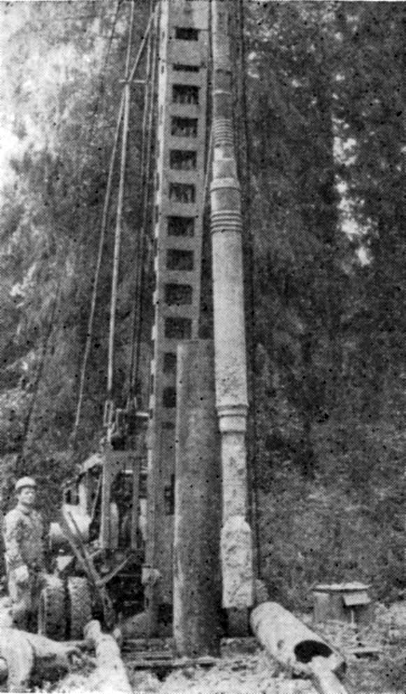
The introduction of percussion-vibration drilling tools into the practice of drilling water wells has shown that their use increases the speed of continuous penetration in hard rocks by 1.5–3 times and eliminates cases of bit jamming by rock fall. An important advantage of percussion-vibration tools of these series is that their effective utilization is achieved using traditional operating methods and technologies for cable-tool percussion rigs.
Regarding cohesive rocks represented by clay soils of varying hardness and plasticity, during cable-tool drilling in [cohesive soils], progress using standard tools—such as bailers, core barrels, or alternating chisel bits and bailers at the bottom of the borehole—is highly inefficient.
The most rational way to increase the excavation rate of cohesive soils during cable-tool drilling is to use high-performance vibro-grabs with longitudinal-rotational action under such geological conditions. However, existing vibro-grabs are electric-powered machines and, given the difficulties of providing power to the bottom of a borehole, they cannot be recommended for use in cable-tool drilling of water wells characterized by a fairly deep depth and relatively small diameter. In connection with this, VNIIGS proposed [26] using the drilling rig’s steel cable—which performs 50 oscillations/minute with an amplitude of 0.5–1.0 m—to drive a submersible soil-excavating vibration machine.
A specific feature of this machine’s operation is that its vibration exciter can only be set in motion while at the bottom of the borehole and cannot be turned on while unloading soil at the surface. This required the creation of a new type of opening soil sampler. Based on these proposals, VNIIGSe experimentally substantiated the feasibility of developing a new type of tool for cable-tool drilling rigs—the impact-vibration bailer (V. V. Verstov, P. I. Larionov, 1980). It was established that the most rational vibration exciter for such a bailer is an inertial eccentric mechanism. To drive it, energy is drawn from the reciprocating movements of a rod connected to the drilling rig’s cable on one side, and to a screw-nut-gear transmission system on the other. The impact-vibration bailer (Fig. 87) includes a body with a built-in drive mechanism, a vibration exciter, and a soil sampler.


The accepted structural solution ensures the operation of the impact-vibratory bailer in a mode where the vibro-exciter functions as a spring-loaded impact-vibration hammer with a negative clearance, delivering impacts directly onto the driven element.
This mode of operation makes it possible, under conditions of limited power, to achieve effective impact-vibratory driving of the soil sampler into the rock. This is achieved because the force of gravity of the soil sampler on the ground is significantly reduced, and it is possible to set the mass of the vibro-exciter to exceed the mass of the soil sampler. It also allows setting a static moment of eccentric masses and an angular velocity of their rotation to achieve a sufficient striking velocity of the vibro-exciter striker against the anvil of the soil sampler.
The soil sampler of the impact-vibratory bailer (Fig. 88) consists of a housing that includes an unlocked and a hinged semi-cylinder. Well drilling with an impact-vibratory bailer is carried out in the following manner: The bailer on the instrument wire-rope of the drilling rig is lowered by the soil sampler to the bottom of the well. The vibro-exciter, due to the drive from the reciprocating movement of the rod, is brought into oscillation, and by striking the anvil of the soil sampler, drives it into the rock. As the soil sampler deepens, the instrument winch drum gradually unwinds the wire-rope.
During experimental studies of the operation of the impact-vibratory bailer, the amplitude and frequency of oscillations of the vibro-exciter, housing, and soil sampler were measured. The speed of driving the latter was recorded, and the nature of the changes in the drive force in the wire-rope was captured.
An analysis of the tension curves in the wire-rope (Fig. 89) showed that within a single period of oscillation, the change in the drive force P(t) has an impulse character with a sharp maximum. The oscillation period T can be divided into two phases, t₁ and t₂. The first phase corresponds to the upward stroke of the rod (constituting 0.4T), and the second phase corresponds to the downward stroke of the rod (constituting 0.6T). In turn, the first phase t₁, which is the phase of the working stroke of the rod, can be divided into two components:
- The time t₃, equal to 0.15T, during which the force in the rope increases to a maximum; during this time, the acceleration of the eccentric mechanism to the maximum frequency of rotation occurs, and the vibro-exciter begins to oscillate;
- The time t₄, equal to 0.25T, during which the force in the rope drops abruptly to zero; during this time, the vibro-exciter performs damped impact oscillations.
The data obtained indicate that the magnitude of the drive force is determined by the static and dynamic moments of resistance of the impact-vibratory bailer mechanism.
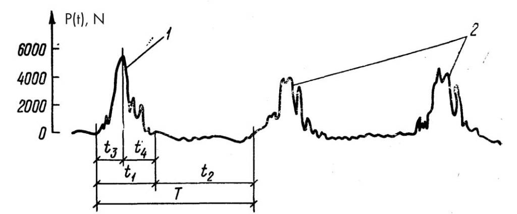
An important experimental result is also the fact that the greatest maximum value of the drive force occurs in the first cycle of operation of the impact-vibratory bailer, during which the eccentrics accelerate. The value of the maximum forces in subsequent cycles is 30% less than the initial value. This means that during the time period from cycle to cycle, there is no stoppage or sharp drop in the rotation speed of the eccentrics.
When evaluating the stability of oscillations of the vibro-exciter, as well as the effectiveness of the impact-vibratory driving of the soil sampler, it was established that during the rotation of the eccentrics from the oscillatory movements of the rope upward, the vibro-exciter, tuned to the operation mode of a spring-loaded impact-vibration hammer, performs periodic damped oscillations and strikes the anvil 3–6 times in one upward stroke of the rope. The highest speed of driving the soil sampler is achieved during the operation of the vibro-exciter in the mode of a spring-loaded impact-vibration hammer with a negative clearance, characterized by sin(α) = 0.4–0.5, and at a specific pressure on the ground of p = 70–85 N/cm².
With fixed parameters of the vibro-exciter, the speed of impact-vibratory driving of the soil sampler v is determined not only by the magnitude of the specific pressure on the ground, but also by the rebounds of the bailer housing. Moreover, a decrease in this magnitude is accompanied by an increase in the driving speed (Fig. 90).

The most preferable regimes are those in which the bailer housing remains relatively motionless during the operation of the system. Taking this circumstance into account, when determining the parameters of the impact-vibratory bailer, it is important to evaluate the driving regime of the housing, which is determined by the ratio of the inertial properties of the housing and all rotating masses of the mechanism.
Theoretical research has established that for the analysed variant of the design of the impact-vibratory bailer, with the maximum possible static moment of the eccentric masses determined from the condition of the required diameter and technologically rational height of the machine, the penetration speed increases with an increase in the rotation frequency of the eccentric weights only with a simultaneous increase in the mass of the housing and a decrease in the bounce height.
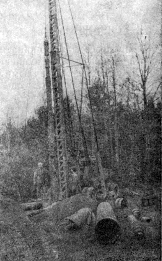
Cable-tool rigs using the trust’s impact-vibration bailer “Promburvod” drilled several wells up to 100 m deep on water. The rock being drilled was represented by loams and clays ranging from plastic to hard, drilling diameters of 325 and 377 mm, interval of depths operated by the impact-vibration bailer from 6 to 60 m.
The impact-vibration bailer (Fig. 91) accelerates the drilling of cohesive rocks by 40–50%, the drilling of which is usually carried out by alternating operation at the bottom of the bit and the bailer. Such an increase in productivity is achieved due to the fact that during drilling it is not required to spend time changing the drilling tool (bit to bailer and vice versa), the need to work in one interval of drilling a well with different tools disappears, the time for unloading the core is reduced, since the operation for turning the bailer upside down to empty it is eliminated.
To implement the drilling of cohesive rocks with an impact-vibration bailer, there is no need to pour water into the well, which is an important technological advantage. The most successful operation of the impact-vibration bailer is achieved in dry soils with a moisture content of the penetrated rocks of 6–10%. To achieve high efficiency of impact-vibration exciting of the core sampler shoes, it is necessary as it deepens into the bottom to maintain zero tension on the working cable of the drilling rig, and for reliable gripping and extraction of the core, the bottom of the core sampler (each half-cylinder) must be equipped with a shoe from a regular bailer of the corresponding size, split along the diameter.
As we can see, the impact-vibration mechanisms considered in this section due to the impact-vibration effect on the rock allow for an increase in drilling productivity while ensuring technological convenience of their application. Impact-vibration drilling tools during the penetration of limestones, marls, dolomites, sandstones, clay shales, and hard clays allow for drilling with a speed of 1.2–3 m/h, whereas conventional drilling tools in these same conditions give a penetration rate of 0.5 to 2 m/h.
When drilling loams, soft- and stiff-plastic clays, the alternating work at the bottom of the bit and the bailer provides a drilling speed of 1.5–2.5 m/h; the use of an impact-vibration bailer for penetrating cohesive rocks of this type increases productivity to 3–3.5 m/h.
When drilling hard and semi-solid clays in dry boreholes or in boreholes with a minimal amount of water, good results are obtained by using a drilling tool that includes an impact rod of the impact-vibration drilling tool VS-1 or VS-2 as a vibration exciter, and as a rock-breaking tool they use a core sampler of an opening type of the impact-vibration bailer VZh-1. Such a combination allows bringing the penetration rate of these rocks to 2–3 m/h due to the intensification of the process of their destruction and the elimination of the use of alternating work at the bottom of the bit and the bailer, which under these conditions can only be carried out by pouring water into the borehole.


One thought on “Driving Through Hard And Cohesive Soils During Impact-Cable Well Drilling In Water”