
For more of this book, click here.
The issue of decommissioning water wells and ground-freezing wells arises in cases where these wells have fulfilled their task (drainage or ground freezing) or their operation (water supply wells) has ceased to be expedient due to a decrease in productivity that can no longer be restored. Solving the issue of decommissioning wells with the extraction of steel pipes from the ground is economically beneficial, as it allows returning scarce casing pipes to the national economy for reuse.
In connection with the need to more fully satisfy the growing needs in well drilling for water supply, dewatering and freezing, it is advisable to utilize additional possibilities for obtaining casing pipes by extracting them from idle wells during their abandonment for subsequent reuse.
Currently, individual organizations of the Ministry of Oil Industry of the USSR, the Ministry of Coal Industry of the USSR, and the Ministry of Transport Construction of the USSR have accumulated some experience in extracting pipes from wells. For this purpose, static equipment (winches, derricks, jacks) is used in most cases. The main disadvantage of static extraction is frequent breaks of casing strings, as a rule, at coupling joints, resulting from significant pulling forces (hundreds of tons) required to overcome the soil friction forces against the pipe. The task of pipe extraction becomes even more complicated during the abandonment of water supply wells, the casing strings of which may remain in the ground for two to three decades.
Studies by VNIIGS and NIIOSP, conducted in the 1960s, showed that the use of vibration for extracting casing pipes from idle wells significantly reduces static lifting forces to values slightly exceeding the dead weight of the extracted pipe string. At the facilities of the “Soyuzshakhtoosushenie” trust, an experimental extraction of pipes with a diameter of 273–426 mm was carried out using the VNIIGS vibratory hammer of the VIOT-1 type from several wells up to 100 m deep (Fig. 115) after their 10-year stay in the ground, and the suitability of the extracted pipes for reuse in drilling was established.
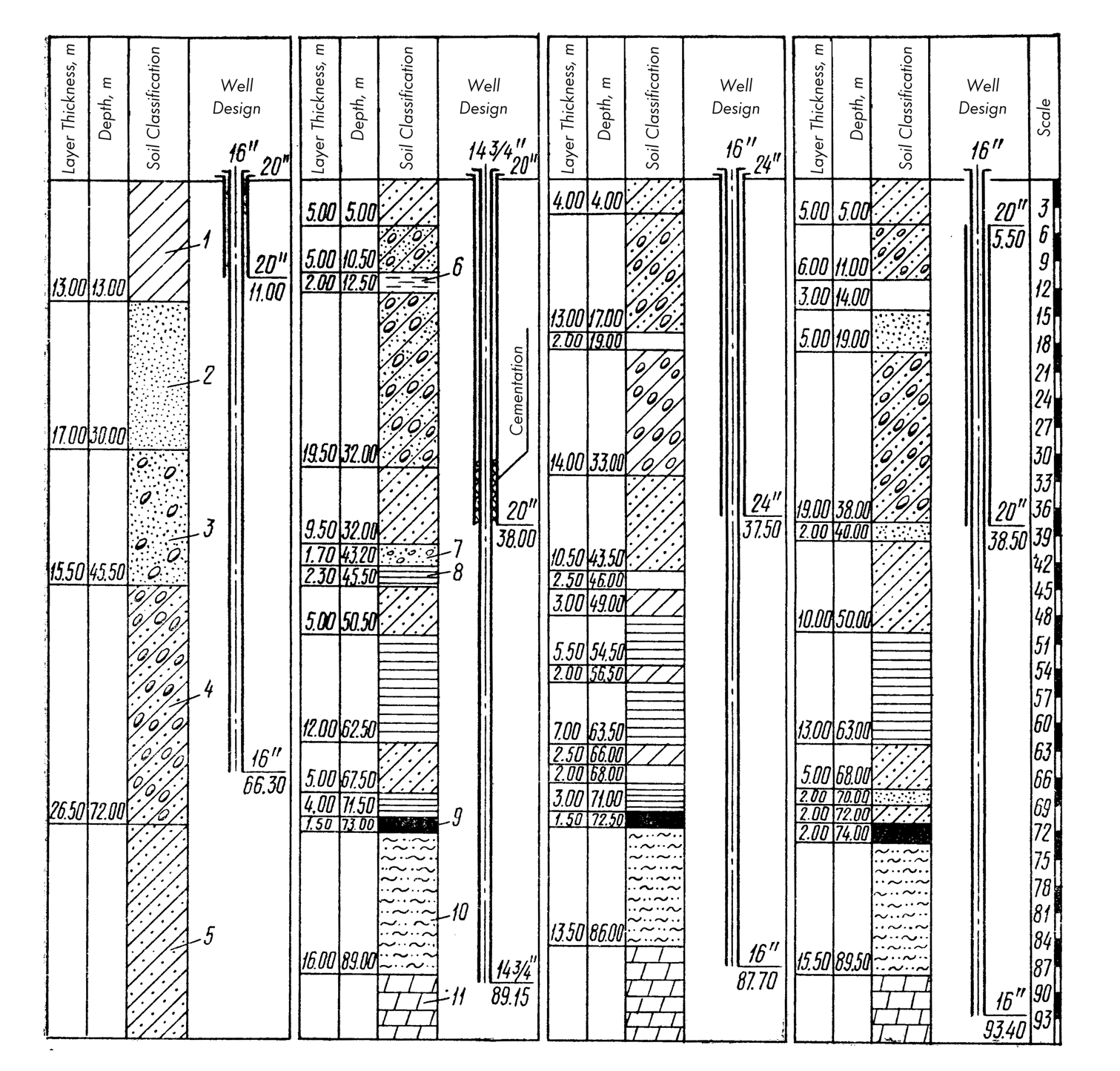
1 — loam; 2 — sand; 3 — sand with inclusion of boulders; 4 — clay with boulders; 5 — sandy clay; 6 — aleurolite; 7 — sandstone; 8 — plastic clay; 9 — brown coal; 10 — Likhvin clay; 11 — dolomite.
To study the technological characteristics of the casing pipe extraction process and obtain comparative data on the efficiency of purely static pulling and pipe extraction by static force combined with vibration and impact-vibration action, an experimental study was performed by VNIIGS. During this study, pipes with a diameter of 159 mm and a length of 5.5 m were extracted from sandy-loam soil.
Figure 116 shows experimental graphs of changes in static pulling force over time for various methods of pipe extraction, from which it can be seen that the patterns of changes in force are identical for both purely static extraction and various types of vibration actions. Using the example of the static pulling curve, let us consider the characteristic features of the process. On section a, the pipe moves statically, and the static pulling force increases; at point a, the pipe begins to move relative to the ground, and section a-a’ is characterized by accelerated extraction of the pipe and a gradual decrease in static force.
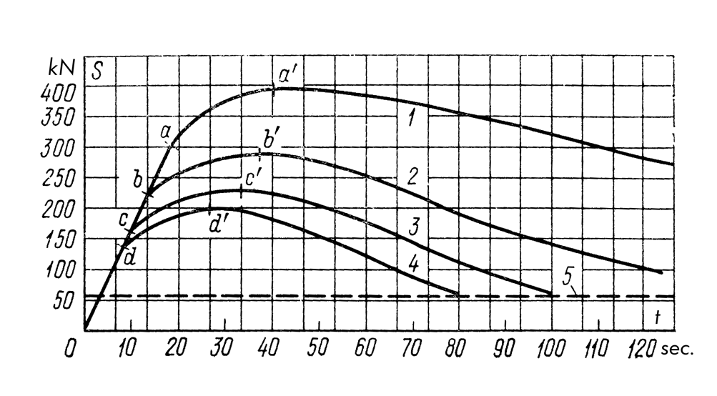
1 – Extraction using only static force;
2 – Extraction under the combined action of static force and a vibrator;
3 – Extraction under the combined action of static force and a dual-strike impact-vibration hammer with upward impacts;
4 – Extraction under the combined action of static force and a single-strike impact-vibration hammer with upward impacts.
Letters a, b, c, d represent points characterizing the force at which forward motion of the pipe begins; a’, b’, c’, d’ represent points characterizing the maximum force.
At point a’, the force reaches its minimum value, and the rate of extraction becomes equal to the speed of the crane pulling winch hook. Further along section a’-a”, pipe extraction occurs at a constant speed, and the static force monotonically increases to values close to the total weight of the heavy pipe string and the vibratory mechanism (dashed line on the graph).
A comparison of the curves in Fig. 116 shows that during the operation of a double-acting vibratory hammer with upward and downward impacts, pipe extraction occurs with the least force, and the decrease in force at a constant extraction speed occurs most intensely.
When using static tension, these performance indicators are at their lowest; the operation of a vibrator and a impact-vibration hammer with upward impacts is characterized by forces that are significantly lower than during static tension, but greater than with a dual-strike impact-vibration hammer.
The highest average pipe extraction speed was obtained during the operation of a dual-strike impact-vibration hammer, followed by a single-strike impact-vibration hammer, a vibrator, and finally, purely static action. Regarding the power consumed by the drive of the vibro-mechanisms, the vibratory method holds an advantage over the impact-vibratory method. Furthermore, purely vibratory machines possess greater durability and are simpler to operate.
Experimental research and industrial experience show that from the standpoint of widespread adoption, the most rational method for extracting casing pipes from defunct wells is a combined method that couples a static load on the pipe string with vibratory action.
Currently, various types of vibratory machines are available, which can be utilized to implement this method.
At several hydraulic engineering and water management construction sites, operations were conducted to extract casing pipes using the VPP-2 and VPP-4 vibro-pilers designed by VNIIGS, as well as vibratory machines designed by VNIIPodzemgaz (VM-56, VIT-60). The “Soyuzshahtoosusheniye” Trust successfully utilized a setup for extracting casing pipes with the VIP-22 vibrator. The development by VNIIGS of the BBS-1 impact-vibration hammer has also found application, enabling the extraction of casing pipes with diameters of 219–530 mm from wells up to 100 meters deep in a vibratory mode.
A conducted technical and economic analysis showed that to improve the cost-efficiency of the extraction process and enable the re-use of pipes, it is highly practical to create autonomous mobile rigs equipped with lifting gear and vibratory tools. These should be capable of performing the entire cycle of operations for decommissioning defunct wells (pipe extraction and wellbore plugging) with maximum mechanical efficiency.
Taking these requirements into account, and building upon existing experience in applying vibratory technology, VNIIGS has proposed technological layouts and equipment composition variants for decommissioning wells of varying depths while extracting casing pipes of different diameters (Table 21).
| Well Depth, m | Pipe Diameter, mm | Maximum Mass of Extracted Pipe String, tons | Lifting Equipment | Vibratory Machine |
|---|---|---|---|---|
| 20 | Up to 114 | 400 | Vibro-pulling unit AVB-2M | VB-7 |
| 50 | 168–426 | 3,000 | Unit for well development and repair A-50U with GD-40 hydraulic jacks | VPF-2 |
| 80 | 219–530 | 6,000 | Aggregate repair rig RA-15 Unit for extracting casing pipes ONT-1 | BBS-1 BBS-1 |
| 100 | 219–530 | 10,000 | Unit for well repair and drilling A-50U | VSh-1 |
Figure 117 illustrates a schematic setup for extracting casing pipes based on the AVR-1 rig, mounted on a chassis 1, which features welding equipment 2, a oil pumping station 3, an electrical generator 4, a heavy-duty winch 5, and a support mast 6 equipped with a lifting mechanism. Pipe extraction is carried out using a VPF-2 vibrator 8, which is secured to the pipe string via a hydraulic clamp. The static pulling force is transmitted to the extracted pipe through a traverse 9, which is attached to the housing of the hydraulic clamp. Shock-absorbing springs are connected to a movable ring 10, which moves along the stem of the hydraulic jacks GD-40 (11), mounted at the wellhead on a support ring 12.
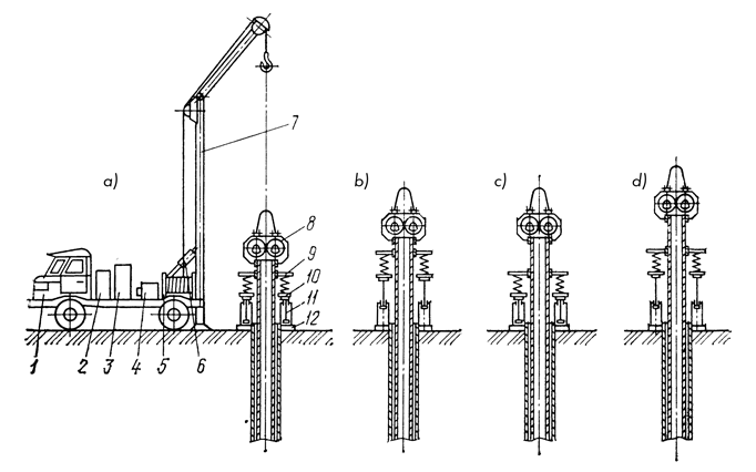
a – installing the vibrator and hydraulic jacks onto the column;
b, c – vibro-extraction of the column;
d – repositioning the grip of the hydraulic jacks.
Scope of application for the rig: Liquidation of single water supply wells up to 50 meters deep.
The vibratory extraction of the pipe is performed with periodic repositioning, which is determined by the working stroke of the hydraulic jacks. Transportation of the vibrator and hydraulic jacks is managed via a trailing trailer. Thanks to the use of hydraulic jacks for generating pulling forces, this type of setup remains lightweight, mobile, and low-energy-intensive.
Figure 118 shows the technological operational sequence of a rig mounted on a tractor base 2. It is equipped with a support device 5, a platform for placing extracted pipes 1, and a double-drum winch 4. One of the drums provides power to the pulley system. It is also equipped with welding equipment 3. To install the vibrator 6 and dismantle the casing column, a mechanical drive cap 7 is used. The drive for all mechanisms of the installation (vibrator 6, winch 4, etc.) is powered by an electrical grid through a control panel 8. It is also possible to replace the diesel engine on the tractor with an electric one. Such a solution is implemented in the OIT-1 pipe extraction rig, which uses a BBC-1 impact-vibration hammer configured for vibrational mode as its vibratory equipment.
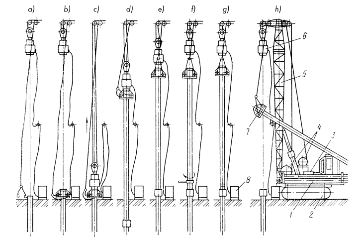
a – initial position;
b – installing the drive cap onto the column;
c – installing the vibrator;
d – vibro-extraction of the column;
e – disconnecting the vibrator;
f – unscrewing the extracted tube;
g – disconnecting the tube from the column;
h – stacking the extracted tube.
Studies by Glavtonnelmetrostroy of the Mintransstroy USSR showed that the rational application zone for the OIT-1 rig consists of construction sites with a significant number of water-lowering wells requiring liquidation.
Figure 119 shows a diagram of a rig built on the base of a KrAZ heavy truck. Mounted on its chassis are welding equipment 2, an electric generator 3, a cargo winch 4, and a support structure 8. The latter can be equipped with a jib 10 and an additional support 9 which increases the stability of the lifting system and allows for an increased lifting capacity to completely unload the vehicle’s frame. Extraction of the pipe is carried out using a vibrator 5, to which a static force from a tackle block 7 is applied through a shock absorber 6. The vibrator is fastened to the pipe by a mechanical gripper. Such a well abandonment scheme with a depth of up to 100 m can be implemented on the basis of the A-50U rig, equipped for pipe vibration extraction with a BSh-1 vibration unit. All variants of the installations given in Table 21 must ensure the production of plugging works by the method of filling the water-bearing stratum with sand, followed by tamping the well shaft with clay and installing a cement plug at the wellhead.
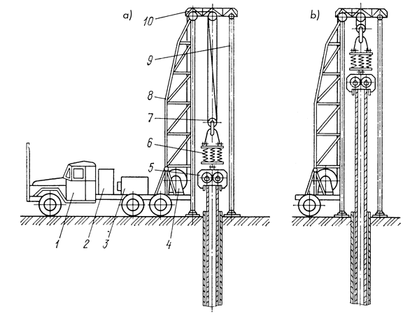
a – installing the vibrator onto the column;
b – vibro-extraction of the column.
According to reporting materials of organizations engaged in drilling wells for water, as well as literary data, VNIIGS carried out a predictive assessment of the possible volumes of work on the liquidation of inactive wells with the extraction of casing pipes. According to this assessment, in the country as a whole, it is annually possible to liquidate up to 10 thousand water supply wells, which will give a saving of about 100 thousand tons of metal. According to calculations, the amount of metal obtained as a result of the liquidation of casing pipes can be up to 20 thousand tons per year.
The introduction of vibration equipment and technologies for the liquidation of inactive wells can serve as a significant factor in increasing production efficiency and saving metal in drilling water wells. On a countrywide scale, this will make it possible to save about 120 thousand tons of metal per year and obtain an economic effect of more than 10 million rubles. Hence it follows that the problem of planning and organizing large-scale work on the liquidation of water wells with the extraction of casing pipes using vibration technology has matured.


One thought on “Casing Pipe Extraction During Well Decommissioning”