
For more of this book, click here.
Currently, various methods are used for constructing trench walls using mainly drilling and grab equipment. One of the promising directions for increasing productivity, reducing costs and increasing the value of this work is the construction of trench walls using vibration technology. The vibration method can be successfully applied both in the excavation of trenches and in their concreting. In this case, the experience of using vibration mechanisms developed at VNIIGS for driving and extracting various elements into the ground, their excavation, as well as concrete placement can be used.
Questions about the use of vibration technology in the construction of trench walls were considered by M. G. Tseitlin, V. E. Trofimov, and I. R. Arabadzhanov (1974). Below are technological diagrams and data on the experience of using vibro-excavators for borehole excavation in the construction of trench walls. One of them is a technological diagram providing for the use of rope grab systems in combination with drilling rigs for drilling leading boreholes.
Instead of drilling equipment for borehole excavation, a longitudinal-rotational vibro-excavator is used. During the construction of an anti-filtration curtain at one of the construction sites, a vibro-excavator of the GPI “Fundamentproekt” design was used in a complex with a flat canvas grab instead of a boring rig for excavating 700 mm diameter boreholes with a depth of 5.5 m. The time spent on drilling each borehole with a vibro-excavator was 25–30 minutes, which provided an increase in productivity of almost 8 times compared to URB-3AM drilling rigs occupied in the same works. At the same time, the amount of clay solution used in drilling boreholes was significantly reduced; pollution of the construction site was practically absent. This was achieved due to the rapid excavation of each borehole to full depth and its subsequent filling with clay solution from a tank mounted on a wheeled trailer (V. E. Trofimov, 1972).
Experience has shown that in cases where the technology for constructing walls provides for the excavation of leading boreholes, it is advisable to carry it out with longitudinal-rotational vibro-excavators.
Longitudinal-rotational vibro-excavators also make it possible to develop trenches in soft soils by the method of intersecting boreholes. Fig. 120 shows one of the possible options for using vibro-excavators in such works. With the help of a vibro-excavator, the first borehole is excavated to the design depth, and a stock tubular element corresponding to the borehole diameter is lowered into it. The tubular element, having a concavity along its length, serves as a guide for drilling the next borehole.
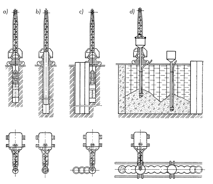
a — driving a pilot borehole with a vibro-excavator;
b — lowering a reusable inventory guiding tubular element;
c — further driving of an adjacent borehole;
d — vibrational placement of concrete via tremie pipes equipped with deep internal vibrators.
When executing a trench excavation, as a rule, two or three interchangeable inventory tubular elements are used alternately. As a specific case study, let us look at the engineering experience of constructing a retaining trench wall via vibro-excavator during the construction of the underground section for the computing center building of the Belorussian Trust “Promburvod” (V. E. Trofimov, V. M. Polotsky, 1978).
The excavation of a foundation pit down to its design depth (9 m) was entirely impossible using standard approaches due to the dense proximity of existing administrative buildings. It was decided to construct a load-bearing retaining wall with a total length of 40 m using the intersecting borehole method with vibrational installation of low-slump concrete mixes.
The drilling of boreholes down to the design depth (9 m) through soils consisting of sandy loams and loams was successfully executed with a vibro-excavator. A truck crane featuring a lifting capacity of 10 tons was utilized as the primary lifting mechanism. The trench development was achieved by sequentially driving boreholes in a “dry” state, each with a diameter of 630 mm. Prior to commencing the driving phase of any subsequent borehole, a leader tubular guide was carefully placed inside the previously drilled borehole. This element performed the role of a temporary casing and provided a guiding path for the drilling process. By shifting these guiding tubular paths along the line of excavation as drilling progressed, workers achieved a highly straight, continuous structure for the trench wall. The extracted soil mass was dumped directly into waiting transport vehicles.
Concreting operations were executed sequentially in individual 3-meter sections. The entire cycle of activities required to build the trench wall was managed effectively by a small crew of only four laborers.
The practical field tests conducted for constructing trench walls out of intersecting boreholes demonstrated that when applying longitudinal-rotational vibro-excavators, this exact technique can be utilized with great success to build trench walls within constrained structural sites situated very close to existing structures.
During the structural deployment of metro lines, trench development was carried out using a specialized flat-shaped vibro-excavator model TB-1, engineered by VNIIGS (V. E. Trofimov, M. Z. Pevzner). This particular vibro-excavator bucket offers a capacity of 1.3 
The total length of the completed trench wall section reached 63 m with a design depth profile of 12.4 m. The underlying soil conditions across the construction sector consisted mainly of moraine loams of a stiff-plastic consistency, transitioning at a depth of 9–10 m into dense loams of a semi-solid consistency. Over the full length of the excavation track at a depth profile of 6 to 7 m, there was a distinctive stratum of large boulders (measuring up to 300 mm). The operations were carried out continuously during winter seasons at freezing ambient temperatures down to -28°C. The complete time frame required to fully submerge into the soil mass (with a bucket capacity of 1.3
The completed construction projects clearly proved the economic and technical viability of leveraging vibro-excavator technology for deep trench building. It is exceptionally promising for execution in damp clayey soils, including formations containing heavy rocky inclusions, because the localized vibrations guarantee reliable self-filling of the bucket assembly during every single cycle. For minor scales of construction work inside heavily confined spaces, it is recommended to execute activities via the intersecting borehole method, utilizing lower-capacity vibro-excavators.
An analysis of the collected field experience demonstrates that driving boreholes with specialized vibro-excavators holds a wide range of clear operational advantages over standard rotary drilling rigs.
Key advantages definitely include:
- Excellent mobility of the applied equipment;
- Fewer number of engaged workers;
- High driving productivity of wells due to the rapid penetration of the soil-grabbing devices;
- unloading of the soil directly into dump trucks and the ability to maintain the cleanliness of the construction site; and
- Vibratory placement in the trench of low-slump concrete mixes, which ensures a reduction in labor intensity of the works and yields dense and durable concrete with a substantial saving of cement.
Figure 121 shows the technological workflow of sinking wells with a concentric excavation using a group of vibro-excavators. The essence of such a technological layout consists in the fact that initially a central core is extracted by a vibro-excavator, and then an annular core is extracted. Discharging the soil into the central part is performed by a driving cutting shoe, which performs longitudinal-rotational oscillations together with the well, imparted by the vibratory driver unit. In Fig. 121, position a shows the vibro-excavator with the central intake section operating inside the well, on which the vibrators are mounted; position b is the moment of soil extraction by the vibro-excavator with the annular intake section; position c is the view of the excavation after the operation of the driving cutting shoe.
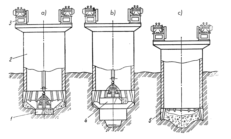
a — vibro-excavator with a central soil intake; 2 — well-casing (shell); 3 — vibratory driver unit; 4 — vibro-excavator with an annular soil intake; 5 — driving cutting shoe.
When sinking a shaft lining, the following sequence of operations was envisioned. After construction of the cutting shoe section, guiding devices with pressure rollers are mounted. The first section is installed on the cutting shoe section and the joint is welded along the outer side. Then the support ring with vibrators is mounted, and vibratory sinking begins. Excavation works are carried out with the support ring removed, and if necessary, without dismantling it. The extension of sections is performed as sinking progresses.
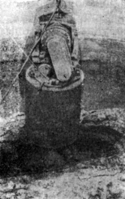
Sinking of the metal shell with a diameter of 4.5 m was carried out by a vibratory driver unit of longitudinal-rotational action, consisting of a support ring and two or four vibrators mounted on it (depending on the size of the driven shells). The general view of the driven lining is shown in Fig. 122.
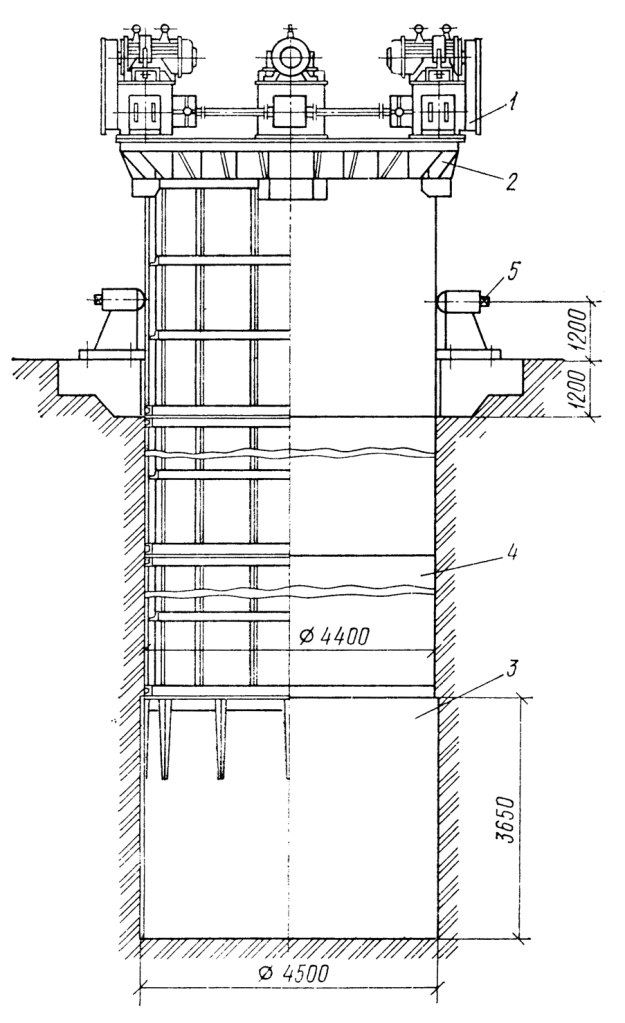
The sinking speed of the first section was 1.8 m/min, and the sinking speed to a depth of 17 m was 0.6 m/min.
Excavation of soil during lining sinking in low-moisture sands and loams was carried out with a minor (up to 1 m) advanced excavation of soil, and in water-saturated sands—with an advanced installation of the lining (by the height of a section). Verticality during the sinking process was ensured by a system of double-tier guides anchored in the collar beams. In the lower tier, wooden beams were used; in the upper tier, guiding devices with press rollers were utilized. Minor deviations from the vertical on individual stages of sinking were eliminated by adjusting the rollers on the side of the tilt and increasing the clearance between the rollers and the lining on the opposite side.
To extract soil during lining sinking, a powerful longitudinal-vibratory grab with a capacity of 56 kW was used, equipped with various types of interchangeable soil-grabbing buckets and a single-rope clamshell grab with a capacity of 0.75 m³. In clay soils, the volume of soil extracted by the vibratory grab per cycle was 2.5–3.5 m³; in sandy soils with stony inclusions, it was 1–2 m³.
By applying the developed methods of vibratory technology, it is possible to increase the speed of work on sinking caissons and reduce manual labor costs. It is especially advisable to use vibratory soil excavation when sinking small-diameter caissons in dense clay soils.
In traditional technology used in such cases, clay is developed manually and loaded into a bucket, which is then lifted to the surface. Low speeds are determined not only by the low productivity of manual labor but also by the limited working front with small caisson dimensions. The use of a vibratory grab for soil extraction allows for the elimination of these disadvantages and ensures an increase in labor productivity by several times.
As a characteristic example, one can point to the experience of sinking an open caisson with a diameter of 4.5 m in dense loams of plastic consistency, which were not amenable to excavation by a conventional clamshell grab. Soil excavation using a vibratory grab allowed for an increase in the sinking speed of the caisson due to the dynamic impact on the soil located under the cutting edge of the caisson. The reduction in the resistance of clay soil subjected to the action of vibration made it possible to utilize a conventional clamshell grab, the operation of which was significantly facilitated.
Due to the use of a vibratory grab at this facility, it was possible to increase labor productivity by 2–2.5 times and practically eliminate manual labor.
For sinking open caissons of large diameter, it is advisable to use a technological scheme that provides for sequential excavation of trenches along the inner walls of the caisson. In this case, the following sequence of operations is adopted (Fig. 123). Initially, from one crane position, an arc-shaped trench (slot) is developed by the vibratory grab, which is formed during the sequential sinking of the grab.
To prevent tilting of the crane, the soil is extracted in such a way that slots consisting of several boreholes are made: first on one side of the crane, and then on the other (on the opposite side of the caisson).
Subsequently, the slots are connected into a single annular trench. The depth of the trench is established depending on soil conditions in such a way as to ensure the sinking of the caisson, but to exclude the possibility of external soil collapse. Such a technology for performing work was first implemented by the LSU trust “Gidrospecfundamentstroy” at the construction site of a pumping station, where a monolithic reinforced concrete caisson with an internal diameter of 10.5 m was sunk using a vibratory grab with a capacity of 1 m³. The work was carried out in clay soils, mostly of soft-plastic consistency. The construction site was serviced by a crane with a lifting capacity of 7 tons. When using the vibratory grab for these operations, it became possible to extract soil in the immediate vicinity of the caisson’s cutting edge.
The adopted scheme of work production provided for making 1 m diameter boreholes along the inner walls of the caisson to a depth of 1.5–2.5 m, with a distance between the axes of 1.7 m, and subsequently joining them into separate arc-shaped slots, leaving soil bridges between the slots. In the resulting annular trench, soil was continuously shifted from under the cutting edge section. In this process, the caisson began to sink, displacing the remaining soil from under the cutting edge into the trench. Simultaneously with the sinking of the caisson, the annular trench was cleared of displaced soil, and preparations were made for the next cycle of work to deepen the annular trench in accordance with the technology described above. Minor tilts of the caisson, occurring during the sinking process, were corrected by additional undermining of soil from under the cutting edge in the diametrically opposite zone of the caisson.
With the help of a vibratory excavator, it is also possible to make leader holes (if necessary, filling them with sand) to reduce soil resistance during caisson sinking. Regulation of the sinking process can be carried out with simultaneous pressing down by means of tensioning anchor ties arranged in the soil in front of the caisson collar, which ensures its verticality.
The use of the described method makes it possible, by reducing the static forces involved in constructing a circular trench, to lighten the design of the anchor tensioning system and speed up the sinking of the well, while maintaining all the advantages of controlled sinking tested in the construction of several facilities.
The application of the developed vibration technology allows solving the following tasks during the sinking of shells and open caissons:
- Soil sinking: ensuring effective sinking of thin-walled shells into the ground;
- Work speed: increasing the speed of work on sinking open caissons by increasing labor productivity several times over when extracting cohesive soils from their cavities.


One thought on “Application Of Vibration Technology In The Construction Of Deep Structures”