
For more of this book, click here.
In non-cohesive soils, cut-off walls such as trench walls with a width of about 0.6 m, as well as thin cut-off walls with a width of 100–200 mm constructed using vibration equipment, have become widespread as anti-seepage barriers. Thin cut-off walls have advantages compared to trench walls: the wall thickness is reduced several times, and the consumption of materials for its construction decreases accordingly; the need to use a thixotropic solution as temporary support disappears; labor costs and construction times are significantly reduced.
The method for constructing thin anti-seepage cut-off walls was proposed in France in the early 1950s to ensure the water tightness of earth dam foundations and consisted of driving and extracting a sheet pile with subsequent filling of the formed cavity in the ground with a hardening solution.
Currently, the most widespread method in global construction practice is the method of constructing thin anti-seepage walls by vibro-driving and subsequent vibro-extraction of one or several metal standard sections. Vibrators of various brands are used as equipment for driving and extracting the sheet pile, depending on the dimensions of the elements and the characteristics of the soil in which the cut-off wall is being built.
As a rule, a widened shoe is placed at the lower part of the sheet pile; inside the latter, injection pipes are placed, which have horizontal outlets at the base of the shoe for injecting solution into the cavity formed in the ground when extracting the element. The process of driving elements is facilitated by injecting solution under the shoe under a pressure of about 0.3 MPa.
In world practice, the most widespread depth of thin walls is about 10 m with a thickness of 10-15 cm; the material used is plastic concrete with a low modulus of deformation, and the production rate ranges from 4 to 12 m³/h.
Development of the technology for constructing a thin anti-seepage wall was carried out by the “Gidrospecstroy” trust of the Ministry of Energy of the USSR in 1968–1969 at an experimental construction site (I. P. Cherny, 1971).
The experimental section, 210 m long, represented a headrace canal of a hydroelectric development. The anti-seepage wall was made to a depth of 7.0 m, with a thickness of 10 cm, cutting into water-resistant clays by 0.5 m.
A narrow trench was created by driving and subsequent extraction using a special piling rig of a metallic beam with an I-section No. 60, connected to a V-401 vibrator. When driving the beam into the face, a solution was simultaneously injected under a pressure of 0.2–0.3 MPa, which ensured the stability of the trench walls and prevented clogging of the injector’s outlet.
The continuity of the wall was ensured by the fact that each subsequent driving of the beam overlapped the previous one by 10 cm, while the solution was displaced from the slot in an average volume of 60 liters with a total consumption per driving of 370 to 450 liters and extraction of the beam. The shift production rate was 70–100 m² of finished wall surface.
The method of constructing thin anti-seepage cut-off walls using vibration equipment was also used to combat water filtration in one of the canal sections (V. B. Kheifits, 1973).
The canal route in this section passes along a hillside with natural slope steepness varying from 1:4 to 1:20, with a relief characterized by erosional incisions along which surface and drained groundwater flow down. The slope is composed of sandy-argillaceous and argillaceous deposits with variations in the elevations of the canal bottom and the foot of the slope of 10-12 m. Water-resistant layers at a depth of 10-12 m from the surface consist of plastic-textured clays, above which lie fine-grained sand, argillaceous, and silty-sandy soils with thin layers of clay and loam and rare inclusions of gravel. In these sandy soils, the canal bed was laid, which required protection during its subsequent operation.
To prevent possible consequences of filtration, a thin anti-seepage cut-off wall was designed, constructed using the vibration technology developed during the construction of the hydroelectric development.
The immersion and extraction of the sheet pile were performed using a V-401 vibratory driver from a rail-mounted self-propelled pile-driving rig, which ensures a depth of anti-filtration curtain of up to 12 m.
A mortar mixer and a pump for supplying the injected mortar to the sheet pile were located on the platform of the pile-driving rig.
The preparation of the mortar was carried out at mechanized mortar mixing stations located along the canal route every 300–400 m. The injected mortar, with a density of 1.53 g/cm³, a slump of 15–17 cm, and a strength of 50–100 N/cm² at 14 days of age, consisted of (per 1 m³): cement — 550 kg, clay — 244 kg, water — 735 l.
Due to the complex ground conditions in which the anti-filtration curtain was constructed, the sheet piles were immersed with a washing action from a pump designed to supply mortar. After passing through such a section 3–5 m long along the curtain route during the reverse stroke of the installation, the process was repeated, but with the injection of the clay-cement mortar.
Depending on the ground conditions, the immersion time of the sheet pile in various areas of the curtain variation ranged from 4–7 to 17–20 min. Labor productivity in the construction of thin anti-filtration curtains using vibratory technology averaged 40 m²/shift.
Thin anti-filtration curtains can be used in combination with trench walls, when required by the conditions of the work execution. An example of the construction of such a complex curtain is the construction of a sludge storage facility for pyritic cinders.
The length of the curtain was 2783 m, and the curtain itself was made in two tiers: the first — to a depth of 7.6–10.7 m from the top of the sand cushion to the design elevations of the bottom of the curtain; the second — to a depth of 2–5.7 m from the top of the primary dam to the curtain of the first tier with an embedment into it of 1 m. The first tier of the anti-filtration curtain was constructed to a depth of 9 m by E-1252 excavators with modernized backhoes. The section of the first tier of the curtain with a depth of more than 9 m and the entire second tier were made by the method of thin anti-filtration curtains.
In a number of cases, to ensure the verticality of the vibratory immersion of the sheet pile, a rigid guiding conductor is used, equipped with a movable frame for installing the sheet pile. The movable frame moves along the conductor with a specific step; this guarantees the overlapping of the previous immersion by a value of about 100 mm, thickness, and water tightness of the curtain.
According to another technology (Yu. E. Burov, 1979), developed by NIIOsponaviy jointly with Mosvodokanalniiproekt, a thin anti-filtration curtain was constructed, designed to protect foundation pits during the construction period from the inflow of groundwater and from the erosion of soil from under foundations located nearby.
According to this technology, work was carried out in the following order. First, with the help of a rod-puncher connected to a V-401 vibratory driver, several boreholes are created within one grip section. During the immersion of the rod, a template is used to ensure the preservation of the design distance between the boreholes and their verticality.
During the vibratory immersion of the rod-puncher into the borehole, a clay suspension is injected to protect the borehole walls from collapse. Guide rods are immersed into the completed boreholes (through one), in the slots of which the legs of a cutting rod are inserted; the latter is rigidly connected to a vibratory loader and is installed over the free borehole located between the guides. After turning on the vibrator, the cutting rod is immersed into the ground, and to facilitate immersion before the cutting rod lands, a clay mortar is supplied under a pressure of 0.4–0.6 MPa. Upon completion of the immersion process of the cutting rod, a slit 60 mm wide remains in the ground, connecting the guide rods together, and through one of them—with a previously constructed section of the anti-filtration curtain. After the formation of the cavity, the cutting rod is extracted with the simultaneous supply of the filler material for the curtain body, and then, in the same way (with the simultaneous supply of filler material), the guide rod located on the side of the finished section of the curtain is extracted.
Using such equipment and technology from the Mosoblspetstroy-4 trust, for the purpose of preventing water filtration into immersed open caissons, anti-filtration curtains were constructed at five facilities near existing buildings in water-logged soils.
An analysis of foreign and domestic experience in constructing thin anti-filtration curtains for permanent and temporary purposes allowed VNIIG to develop a universal technology for constructing curtains of this type using vibratory equipment (G. G. Azbel, G. N. Nikolskaya, 1982).
According to this technology (Fig. 124), five to ten steel sheet piles are immersed into the water barrier “in interlock” with a depth, and for hanging curtains, their number increases to five to seven. The number of elements used depends on ground conditions: the weaker the ground, the more elements should be in it.
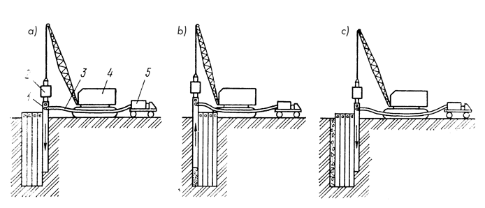
a — driving of sheet pile sections at the beginning of wall construction; b — extraction of the first driven sheet with the filling of the resulting cavity with slurry; c — driving of a previously extracted sheet into the interlocking joint with the edge element; 1 — sheet pile section; 2 — vibrator; 3 — slurry feed hose; 4 — lifting device; 5 — slurry mixing unit
The sheet piles represent a box-like structure in plan, equipped along its entire length with interlocking sheet pile joints, inside of which pipes are passed to feed the injected slurry to an enlarged shoe located at the toe of the pile, which serves as a distribution manifold for this slurry.
During the driving of each element, slurry is supplied to facilitate the driving process and prevent the injection tubes from becoming clogged with soil. The injection pressure in this case is 0.3–0.4 MPa. Upon extraction of the element, the resulting cavity is filled with slurry. The capacity of the pump feeding the slurry (pumps of the 11GR type were used) was determined in accordance with the extraction speed of the element and ensured a continuous supply of slurry so that a pressure of about 0.25–0.3 MPa was maintained at the pump during extraction, indicating the correct progress of the cavity filling process.
The slurry injected into the cavity has an average density of $\rho = 1.3\text{ g/cm}^3$ to prevent the trench walls from collapsing from the moment the element is extracted until the slurry begins to harden. To ensure pumpability, the slurry must possess mobility characterized by a slump flow value (measured with an AzNII cone) within the range of 20–25 cm.
Soil-cement compositions containing Grade 400 cement, averaging about 100 kg per 
Using the technology described above, a number of permanent anti-filtration cutoff walls were constructed in the reclamation systems of Belorussia.
The test results of core samples collected from the filler material of a completed section of the anti-filtration cutoff wall after five months showed that, with a high uniformity of sample strength (coefficient of variation 
Visual inspection of the wall in excavated trial pits established that the cutoff wall is a continuous monolithic body 10–12 cm thick; there were no joints or sections of reduced thickness.
An analysis of domestic and foreign experience in constructing thin anti-filtration cutoff walls shows that the vibratory driving and extraction of sheet piles to form a cavity in the ground was carried out using vibratory machines designed for driving and extracting steel sheet piling. At the same time, due to the presence of the shoe, sheet piles have a significantly larger frontal surface area than steel sheet piles. This means the soil resistance forces during the vibratory driving of elements are substantially greater than for sheet piling, and the construction of thin cutoff walls requires more powerful vibratory drivers than similar sheet piling works.
Experience in constructing thin anti-filtration cutoff walls shows that the scope of application for structures of this type is limited to non-cohesive or water-saturated soils, as well as soft-plastic clays. To expand the scope of application for thin walls under difficult geological conditions involving interbedded layers of various soils, it is necessary not only to use a powerful driving mechanism but also to ensure the dynamic stability of the sheet piles. To achieve this, its optimal dimensions must be determined in each specific case, coordinating them with the vibration parameters and the dimensions of the vibratory driver.
The continuous nature of the construction process for a thin anti-filtration cutoff wall and the demands of the method’s technical and economic efficiency dictate the necessity of ensuring high speeds for connecting and disconnecting the vibratory driver with the sheet pile, and these operations must be performed with a high degree of mechanization.
The output and quality of wall construction work depend significantly on the correct selection of lifting and auxiliary technological equipment intended for preparing the injected slurry. First and foremost, this applies to the ratio between the speed of the hoisting operations performed by the crane and the output of the slurry feed pump. The pump capacity must be 10–15% higher than the extraction speed of the sheet pile multiplied by its cross-sectional area (in the corresponding units of measurement and the capacity of the equipment for grout preparation) must equal the maximum capacity of the pump. Meeting the first requirement ensures the continuity and uniformity of the finished wall along its height, while meeting the second ensures no interruptions in operation due to a shortage of injected grout.


One thought on “Construction Of Thin Anti-Seepage Cut-Off Walls”