
More Resources
- Foundation Design and Analysis: Deep Foundations, Pile Dynamics
- Design and Construction of Driven Pile Foundations, 2016 Edition. The second volume covers this topic.
Overview
Now we come to the topic that was the genesis of this and the related sites: pile dynamics. There’s quite a lot on the subject, so an extensive review of the subject here is unnecessary. Below are some of the many articles I have written on the subject over the years:
- Historical Pieces, from the Dynamic Formulae to the Present
- Before Wellington and ENR: Early Dynamic Formulae, and Sanders’ Formula
- The Engineering News Formula, and Its Treatment in Early Vulcan Literature
- Isaacs and Glanville: The Beginnings of the Wave Equation for Piles
- A Sea Fight in a Fog: Revisiting the ASCE Controversy about Dynamic Formulae
- Vulcan and Dynamic Formulae
- Smith’s Wave Equation Program–the first numerical method
- TTI Wave Equation Program, with MICROWAVE Program
- WEAP: Wave Equation Analysis of Pile Driving, with SPILE, Estimation of Pile Ultimate Capacity
- TNOWAVE and the Method of Characteristics
- Topical Pieces
- Introduction to Wave Mechanics in Piling
- The Case Method: An Overview and Worked Example
- ZWAVE, Vulcan’s own wave equation program in the 1980’s
Closed form solution of the wave equation for piles, the definitive work on the subject, from the 1990’s. Includes some of the background documents and derivative works.
Improved Methods for Forward and Inverse Solution of the Wave Equation for Piles, a 3D FEA solution of the wave equation, with many referenced documents - My Perspective on Driven Pile Drivability Studies
Pile dynamics has always been a difficult subject for two reasons: a) civil engineers panic when something moves (well, that’s what I always told my students) and b) it involves the use of one or more computer programs, which add to the “black box” aspect of the whole thing. My articles above are attempts in part to clear up some of the mystery, and this piece and the one that follows will be more attempts to do the same.
Worked Example
The best way to illustrate this is with a worked example. For this purpose I will use the WEAP87 program, which is discussed in detail (with download link and extensive manual) in my post WEAP: Wave Equation Analysis of Pile Driving, with SPILE, Estimation of Pile Ultimate Capacity. Again, as with the lateral loads, you’re planning on making a living out of this, I recommend you take a look at a contemporary version, in this case GRLWEAP. Although much of the theory behind the program is the same as with WEAP87, GRLWEAP automates much of the work in putting the model together, and is designed to be used with contemporary computers. It also incorporates a version of the DRIVEN software to estimate the SRD (soil resistance to driving) of the pile.
In the post Driven Pile Design: Three Methods of Analysis the “ultimate bearing capacity” is computed three ways. For this analysis the DRIVEN solution will be used, not only because it is more like what GRLWEAP would estimate but because it makes it easier to illustrate the difference between the ultimate bearing capacity and the SRD. Let us look at the three stages of driving and the resistance that occurs for each below.
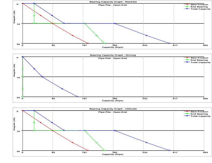
Starting from the bottom, the ultimate capacity is shown for both shaft and toe resistance for every point from the surface to the design tip elevation of 30′. The driving resistance (SRD) is shown in the middle graph, which is substantially lower than the ultimate design capacity of the pile. At the top is the restrike SRD, which is identical to the ultimate capacity. This is intentional; the idea is to restrike the pile (with appropriate instrumentation) around a month after the original driving so that the soil has “set up” after driving and is back to approximately its final ultimate capacity.
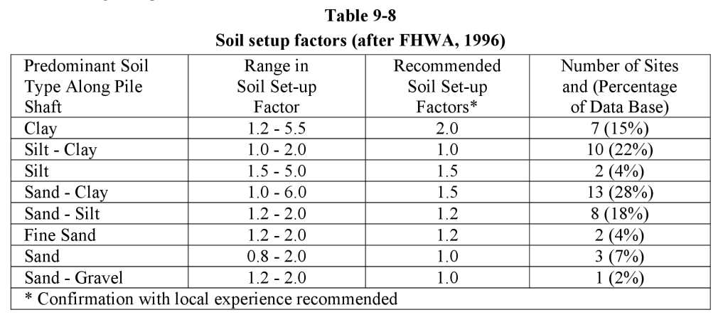
Pile set-up is a complex phenomenon and has a number of factors which influence it (including, believe it or not, the blow rate of the hammer) but whose main cause is the increase in pore water pressures during driving, which lower the effective stress around the pile and thus the shaft resistance. These affect mainly clays because their low permeability do not allow for the quick dissipation of the pore water pressures. A quick table of the ratio of restrike/ultimate capacity and SRD during driving (set-up factor) is shown below.
So how do we deal with this? We could use the data from the “driving” SRD, but a simpler way is to use the bearing graph approach. We set the restrike SRD as the “ultimate” and choose a series of SRD’s (including the driving SRD or some around it) to see what SRD at which the blow count becomes excessive. At the right is a diagram showing the set of the pile for each blow, which is the inverse of the blow count, or blows per foot or metre of pile penetration.
Having made this assumption, we construct the model in WEAP87 using the following parameters (refer to the documentation on how this is actually done):
- Hammer
- Vulcan 08. The documentation has all of the parameters needed for input.
- Hammer cushion: standard cushion pot with micarta and aluminium cushion. An important note about micarta and aluminium cushion for Vulcan hammers is here.
- Pipe cap: standard Vulcan pipe cap.
- Refusal blow count specifications for Vulcan hammers is here.
- Pile
- 18″ O.D. x 1/2″ wall x 30′ long steel pipe pile, open ended.
- Soil
- Soil profile as previously shown. The DRIVEN results will be used for this analysis.
- Instead of a detailed input (which is possible with WEAP87,) a simplified input will be used which assumes the following:
- Triangular distribution of shaft resistance
- Shaft resistance starts at pile head
- A “homogenised” damping of 0.15 sec/ft is assumed which considers the effects of both cohesive and cohesionless soils. Damping is probably the single most important variable in this problem and needs to be chosen carefully.
- The shaft quake is assumed to be 0.1″; the toe quake is 0.15″, which is appropriate for 18″ piles.
- A range of SRD’s from 50 to 500 kips is chosen for the bearing graph analysis.
All of this is input into WEAP87. GRLWEAP automates a good deal of this, although you need to look over the parameters it chooses carefully. The input file is as follows:
18" Pile for Academic Purpose
0 0 207 0 0 0 6 0 0 0 45 0 1 0 0 0 0 0
1.55 148.49 350.00 8.5000 .8000 .0100 0.
.00 .00 .0000 .5000 .0100 0.
30.00 27.49 30000.00 492.00 .8500 .0100
.000 .000 .0 .0000 .0000
.1000 .1500 .1000 .1000
50.00 100.00 150.00 200.00 250.00 300.00 350.00 400.00
450.00 500.00
The output file is as follows:
1 WEAP87: WAVE EQUATION ANALYSIS OF PILE FOUNDATIONS
1987, VERSION 3.00
        18" Pile for Academic Purpose

         HAMMER MODEL OF: VUL   08 MADE BY: VULCAN

   ELEMENT     WEIGHT  STIFFNESS  COEFF. OF    D-NL.   CAP DAMPG
               (KIPS)   (K/IN)   RESTITUTION    FT      (K/FT/S)
          1     8.000
   CAP/RAM      1.550    5935.2      .800     .0100       5.3

   ASSEMBLY     WEIGHT STIFFNESS   COEFF. OF   D-NL.
                (KIPS)   (K/IN)   RESTITUTION   FT
          1     4.940   30280.5
          2     4.940   30280.5      .800     .0100

   HAMMER OPTIONS:
    HAMMER NO. FUEL SETTG. STROKE OPT. HAMMER TYPE DAMPNG-HAMR
     207           1           0           3           2

   HAMMER PERFORMANCE DATA
    RAM WEIGHT  RAM LENGTH   MAX STROKE     STROKE   EFFICIENCY
      (KIPS)          (IN)        (FT)         (FT)
          8.00       50.00        3.25        3.25        .670

    RTD PRESS.   ACT PRESS.   EFF. AREA  IMPACT VEL.
      (PSI)          (PSI)       (IN2)       (FT/S)
           .00         .00         .00       11.84


    HAMMER CUSHION    AREA   E-MODULUS    THICKNESS   STIFFNESS
                     (IN2)       (KSI)         (IN)   (KIPS/IN)
                    148.49       350.0       8.500      6114.3
1
PC-WEAP87 REVISED JUNE, 1988 FHWA 18" Pile for Academic Purpose
   PILE PROFILE:
       LBT    AREA    E-MOD     SP.W.    WAVE SP     EA/C
      (FT)   (IN2)    (KSI)   (LB/FT3)    (FT/S)   (K/FT/S)

       .00    27.5   30000.   492.000   16806.8      49.1
     30.00    27.5   30000.   492.000   16806.8      49.1

             WAVE TRAVEL TIME - 2L/C - =   3.570 MS


            PILE AND SOIL MODEL FOR RULT =     50.0 KIPS
NO WEIGHT STIFFN D-NL SPLICE COR SOIL-S SOIL-D QUAKE L BT AREA
(KIPS) (K/IN) (FT) (FT) (KIPS) (S/FT) (IN) (FT) (IN**2)
1 .470 13745. .010 .000 .850 .6 .100 .100 5.00 27.5
2 .470 13745. .000 .000 1.000 1.9 .100 .100 10.00 27.5
3 .470 13745. .000 .000 1.000 3.1 .100 .100 15.00 27.5
4 .470 13745. .000 .000 1.000 4.4 .100 .100 20.00 27.5
5 .470 13745. .000 .000 1.000 5.6 .100 .100 25.00 27.5
6 .470 13745. .000 .000 1.000 6.9 .100 .100 30.00 27.5
TOE 27.5 .100 .150
   PILE OPTIONS:
   N/UNIFORM  AUTO S.G.  SPLICES  DAMPNG-P   D-P VALUE
                                              (K/FT/S)
        0         0         0         1          .981

   SOIL OPTIONS:
    % SKIN FR  % END BG   DIS. NO.  S DAMPING
       45        55         1        SMITH-1

  ANALYSIS/OUTPUT OPTIONS:
  ITERATNS  DTCR/DT(%)  RES STRESS    IOUT  AUTO SGMNT OUTPT INCR  MAX T(MS)
       0        160          0          0          0          1          0
1
PC-WEAP87 REVISED JUNE, 1988 FHWA 18" Pile for Academic Purpose
RULT = 50.0, RTOE = 27.5 KIPS, DEL T = .158 MS
NO. FMIN,JMN FMAX,JMX STRMIN,JSN STRMAX,JSX VMAX,JVX DMAX,JDX
(K) (K) (KSI) (KSI) (F/S) (IN)
1 .0, 0 518.4, 22 .00, 0 18.86, 22 15.6, 45 2.015,278
2 -90.1, 42 519.2, 24 -3.28, 42 18.89, 24 14.0, 43 2.013,278
3 -113.9, 41 517.9, 26 -4.14, 41 18.84, 26 14.1, 40 2.010,278
4 -102.1, 40 500.1, 28 -3.72, 40 18.19, 28 15.1, 37 2.006,282
5 -64.1, 39 429.8, 29 -2.33, 39 15.64, 29 16.7, 35 2.005,285
6 -17.1, 61 264.0, 29 -.62, 61 9.60, 29 18.6, 34 2.004,285
1
PC-WEAP87 REVISED JUNE, 1988 FHWA 18" Pile for Academic Purpose
RULT = 100.0, RTOE = 55.0 KIPS, DEL T = .158 MS
NO. FMIN,JMN FMAX,JMX STRMIN,JSN STRMAX,JSX VMAX,JVX DMAX,JDX
(K) (K) (KSI) (KSI) (F/S) (IN)
1 .0, 0 520.1, 22 .00, 0 18.92, 22 11.6, 43 1.118,159
2 -7.2, 42 521.3, 24 -.26, 42 18.96, 24 11.5, 41 1.116,159
3 -9.8, 41 519.6, 26 -.36, 41 18.90, 26 12.0, 39 1.114,158
4 .0, 0 500.6, 28 .00, 0 18.21, 28 13.2, 36 1.111,157
5 .0, 0 430.2, 29 .00, 0 15.65, 29 15.2, 33 1.107,157
6 .0, 0 268.6, 29 .00, 0 9.77, 29 16.6, 33 1.103,157
1
PC-WEAP87 REVISED JUNE, 1988 FHWA 18" Pile for Academic Purpose
RULT = 150.0, RTOE = 82.5 KIPS, DEL T = .158 MS
NO. FMIN,JMN FMAX,JMX STRMIN,JSN STRMAX,JSX VMAX,JVX DMAX,JDX
(K) (K) (KSI) (KSI) (F/S) (IN)
1 .0, 0 522.0, 22 .00, 0 18.99, 22 10.7, 23 .797,122
2 .0, 0 523.5, 24 .00, 0 19.04, 24 10.6, 25 .789,123
3 .0, 0 521.3, 26 .00, 0 18.96, 26 10.6, 37 .782,125
4 .0, 0 500.8, 28 .00, 0 18.22, 28 12.0, 35 .775,127
5 .0, 0 429.8, 29 .00, 0 15.64, 29 14.0, 33 .769,127
6 .0, 0 275.2, 30 .00, 0 10.01, 30 15.0, 32 .762,127
1
PC-WEAP87 REVISED JUNE, 1988 FHWA 18" Pile for Academic Purpose
RULT = 200.0, RTOE = 110.0 KIPS, DEL T = .158 MS
NO. FMIN,JMN FMAX,JMX STRMIN,JSN STRMAX,JSX VMAX,JVX DMAX,JDX
(K) (K) (KSI) (KSI) (F/S) (IN)
1 .0, 0 523.6, 22 .00, 0 19.05, 22 10.6, 23 .630,106
2 .0, 0 525.5, 24 .00, 0 19.12, 24 10.5, 25 .619,106
3 .0, 0 522.6, 26 .00, 0 19.01, 26 10.3, 27 .608,105
4 .0, 0 500.5, 28 .00, 0 18.21, 28 11.1, 34 .597,104
5 .0, 0 429.1, 29 .00, 0 15.61, 29 13.1, 32 .587,104
6 .0, 0 281.2, 30 .00, 0 10.23, 30 13.8, 32 .578,104
1
PC-WEAP87 REVISED JUNE, 1988 FHWA 18" Pile for Academic Purpose
RULT = 250.0, RTOE = 137.5 KIPS, DEL T = .158 MS
NO. FMIN,JMN FMAX,JMX STRMIN,JSN STRMAX,JSX VMAX,JVX DMAX,JDX
(K) (K) (KSI) (KSI) (F/S) (IN)
1 .0, 0 521.9, 22 .00, 0 18.99, 22 10.7, 23 .548, 84
2 .0, 0 527.5, 24 .00, 0 19.19, 24 10.5, 25 .530, 86
3 .0, 0 524.8, 26 .00, 0 19.09, 26 10.2, 27 .514, 90
4 .0, 0 502.7, 28 .00, 0 18.29, 28 10.5, 30 .500, 91
5 .0, 0 431.6, 29 .00, 0 15.70, 29 12.3, 32 .487, 92
6 .0, 0 289.8, 30 .00, 0 10.54, 30 12.7, 32 .475, 94
1
PC-WEAP87 REVISED JUNE, 1988 FHWA 18" Pile for Academic Purpose
RULT = 300.0, RTOE = 165.0 KIPS, DEL T = .158 MS
NO. FMIN,JMN FMAX,JMX STRMIN,JSN STRMAX,JSX VMAX,JVX DMAX,JDX
(K) (K) (KSI) (KSI) (F/S) (IN)
1 .0, 0 522.8, 22 .00, 0 19.02, 22 10.6, 23 .493, 76
2 .0, 0 529.5, 24 .00, 0 19.26, 24 10.4, 25 .472, 77
3 .0, 0 526.2, 26 .00, 0 19.14, 26 10.1, 27 .451, 79
4 .0, 0 502.7, 28 .00, 0 18.29, 28 10.2, 29 .432, 82
5 .0, 0 431.2, 29 .00, 0 15.68, 29 11.6, 31 .415, 84
6 .0, 0 327.1, 36 .00, 0 11.90, 36 11.8, 31 .401, 85
1
PC-WEAP87 REVISED JUNE, 1988 FHWA 18" Pile for Academic Purpose
RULT = 350.0, RTOE = 192.5 KIPS, DEL T = .158 MS
NO. FMIN,JMN FMAX,JMX STRMIN,JSN STRMAX,JSX VMAX,JVX DMAX,JDX
(K) (K) (KSI) (KSI) (F/S) (IN)
1 .0, 0 523.6, 22 .00, 0 19.05, 22 10.7, 23 .451, 73
2 -15.4,123 532.6, 24 -.56,123 19.37, 24 10.4, 25 .428, 73
3 -17.4,126 529.3, 26 -.63,126 19.25, 26 9.9, 27 .403, 74
4 -12.4,127 505.2, 28 -.45,127 18.38, 28 10.0, 29 .380, 77
5 -4.1,127 432.8, 29 -.15,127 15.74, 29 11.1, 31 .360, 79
6 .0, 0 361.5, 36 .00, 0 13.15, 36 11.1, 31 .344, 81
1
PC-WEAP87 REVISED JUNE, 1988 FHWA 18" Pile for Academic Purpose
RULT = 400.0, RTOE = 220.0 KIPS, DEL T = .154 MS
NO. FMIN,JMN FMAX,JMX STRMIN,JSN STRMAX,JSX VMAX,JVX DMAX,JDX
(K) (K) (KSI) (KSI) (F/S) (IN)
1 .0, 0 524.8, 23 .00, 0 19.09, 23 10.6, 24 .416, 71
2 -22.3,121 536.2, 25 -.81,121 19.51, 25 10.3, 25 .390, 73
3 -28.3,122 532.4, 27 -1.03,122 19.37, 27 9.8, 27 .363, 73
4 -17.1,122 504.4, 29 -.62,122 18.35, 29 9.7, 30 .336, 75
5 -2.7,124 432.0, 30 -.10,124 15.72, 30 10.6, 32 .313, 78
6 .0, 0 390.8, 37 .00, 0 14.22, 37 10.5, 32 .294, 79
1
PC-WEAP87 REVISED JUNE, 1988 FHWA 18" Pile for Academic Purpose
RULT = 450.0, RTOE = 247.5 KIPS, DEL T = .149 MS
NO. FMIN,JMN FMAX,JMX STRMIN,JSN STRMAX,JSX VMAX,JVX DMAX,JDX
(K) (K) (KSI) (KSI) (F/S) (IN)
1 .0, 0 534.0, 51 .00, 0 19.42, 51 10.6, 24 .388, 58
2 -29.9,120 538.3, 26 -1.09,120 19.58, 26 10.3, 26 .357, 73
3 -38.8,121 534.3, 28 -1.41,121 19.44, 28 9.7, 28 .327, 74
4 -27.5,122 504.7, 30 -1.00,122 18.36, 30 9.5, 30 .298, 73
5 -8.4,124 432.4, 31 -.31,124 15.73, 31 10.2, 32 .273, 67
6 .0, 0 413.5, 39 .00, 0 15.04, 39 9.9, 33 .252, 68
1
PC-WEAP87 REVISED JUNE, 1988 FHWA 18" Pile for Academic Purpose
RULT = 500.0, RTOE = 275.0 KIPS, DEL T = .144 MS
NO. FMIN,JMN FMAX,JMX STRMIN,JSN STRMAX,JSX VMAX,JVX DMAX,JDX
(K) (K) (KSI) (KSI) (F/S) (IN)
1 .0, 0 574.3, 53 .00, 0 20.89, 53 10.6, 25 .370, 58
2 -34.9,121 559.4, 55 -1.27,121 20.35, 55 10.2, 27 .334, 60
3 -45.1,122 542.7, 57 -1.64,122 19.74, 57 9.6, 29 .300, 62
4 -31.9,123 508.4, 59 -1.16,123 18.49, 59 9.3, 31 .268, 65
5 -8.2,125 460.3, 61 -.30,125 16.75, 61 9.8, 33 .239, 68
6 .0, 0 426.2, 41 .00, 0 15.50, 41 9.4, 34 .215, 69
1
PC-WEAP87 REVISED JUNE, 1988 FHWA 18" Pile for Academic Purpose
R ULT BL CT STROKE(EQ.) MINSTR I,J MAXSTR I,J ENTHRU
KIPS BPF FT KSI KSI FT-KIP
50.0 6.4 3.25 -4.14( 3, 41) 18.89( 2, 24) 15.1
100.0 12.3 3.25 -.36( 3, 41) 18.96( 2, 24) 15.5
150.0 18.9 3.25 .00( 1, 0) 19.04( 2, 24) 15.4
200.0 26.6 3.25 .00( 1, 0) 19.12( 2, 24) 15.1
250.0 34.5 3.25 .00( 1, 0) 19.19( 2, 24) 15.0
300.0 43.8 3.25 .00( 1, 0) 19.26( 2, 24) 14.8
350.0 55.5 3.25 -.63( 3,126) 19.37( 2, 24) 14.5
400.0 72.2 3.25 -1.03( 3,122) 19.51( 2, 25) 14.0
450.0 96.5 3.25 -1.41( 3,121) 19.58( 2, 26) 13.4
500.0 136.7 3.25 -1.64( 3,122) 20.89( 1, 53) 13.1
1The program produces a bearing graph summary of the results:
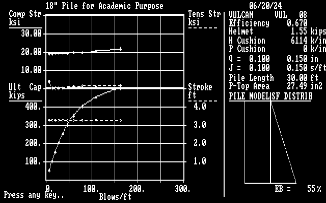
DRIVEN estimated the restrike SRD to be around 400 kips. The bearing graph (and the text output) shows that the blow count at this SRD is 72.2 blows/foot, which is within Vulcan’s refusal criterion of 120 BPF. Obviously with relaxation and set-up the blow count during driving should be lower. The bearing graph results can be used for a blow count acceptance of the pile if something that simple is acceptable.
Another parameter shown in the bearing graph is the maximum tension and compression stresses in the pile. These should be compared with the table below. Note that maximum stresses during pickup, driving and actual service are different. It is easy to see that the driving stresses are within these criteria for any grade of steel commonly used in piling.

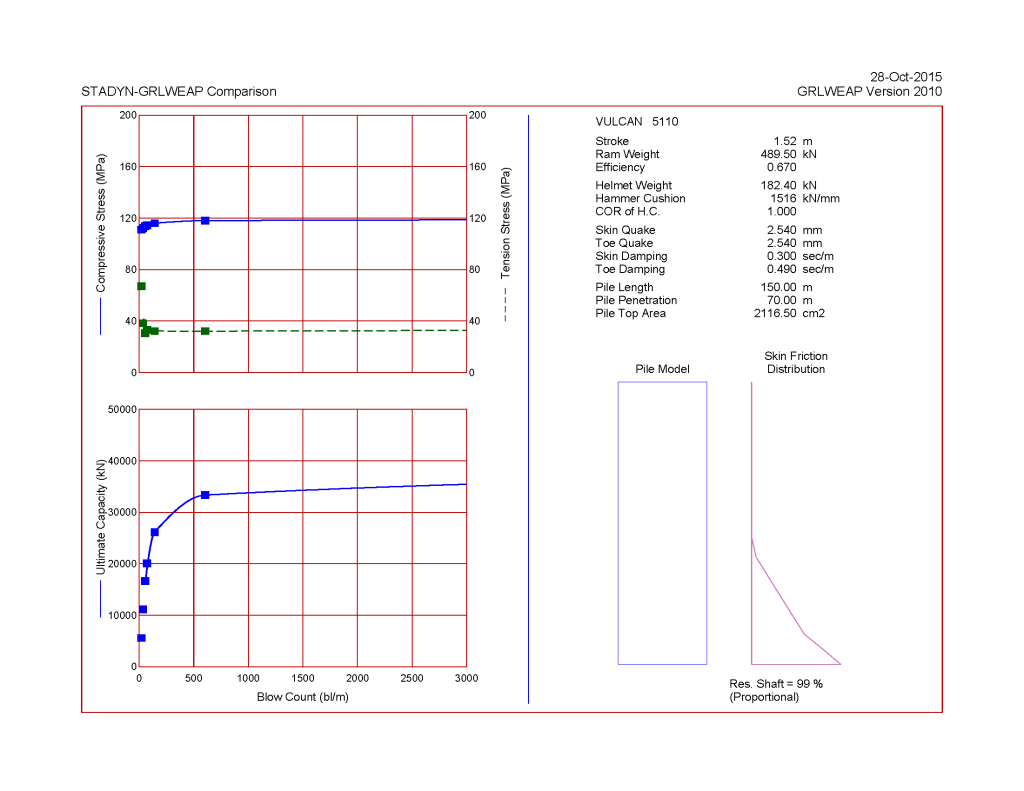
Soils in Construction has another example of this using GRLWEAP. Still another example of this can be found in Improved Methods for Forward and Inverse Solution of the Wave Equation for Piles, and the bearing graph results for this can be seen below.


3 thoughts on “Driven Pile Design: Wave Equation Analysis”