
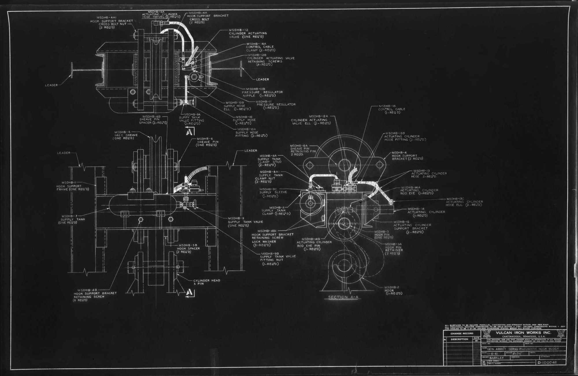
In the early 1960’s Vulcan became involved with the Sand Drain hammers. Part of that effort was developing a servo-pneumatic hook block to grab and lift the hammer and everything else what was attached to it. The device is shown above. Vulcan received a patent for it.
Here we’ll concentrate on one aspect: the design of the hook itself, and specifically the hook as a curved beam. It is shown below; the hook is a 4″ thick plate. Being a plate means that the cross-section of the hook is rectangular, which is unusual for lifting hooks of this kind. The importance of the rectangular cross-section is that the solution for other cross-sections are based on its solution.

The applied load P is simple; when loaded it transmits from the top pin to the bottom, the forces depicted by the arrows.
The problem of curved beams with rectangular cross sections was first formulated by Kh. S. Golovin in 1880. Because the solution was in Russian, it was not widely known outside of Russia until it was disseminated by Timoshenko (Timoshenko and Goodier, 1951).) The solution here is based on Belyaev. It is not meant to be a complete derivation but an outline.
The Basic Equations
The first thing we do is to present the nomenclature, which is below in the two diagrams.

First we define three important radii. The first is R1, the outer (large) radius. The second is R2, the inner (small) radius. The third is R0, the radius of the centroid of the rectangular cross section, which is obviously

The difficult part of the curved beam analysis is that the neutral axis is not located at R0, even for a rectangular cross-section like this one. The curvature of the beam shifts the neutral axis from the centroidal one by the offset z0. This also means that the distribution of stresses between the extreme fibres is not linear, unlike a straight beam.
For a hook like this (and this is true for many curved beams) the stresses normal to the critical plane (shown in Figure 1) is both axial and bending, as given by the equation

We first define S, which is the result of the stress integration from R2 to R1. That integration is described in Belyaev. It is

where A is the cross sectional area, given by

also

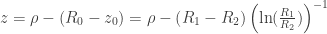
and z0 is


The variable 

Making all of the substitutions for Equation (2), we have at last

where

It is obviously possible to skip the last step and do the variable computations separately; an example will be presented at the end to demonstrate this. Equation (8) is obviously best suited for, say, a spreadsheet.
The Sand Drain Hook Example
Looking at Figure 1, we can deduce the basic parameters as follows:
- R1 = 5 5/8″
- R2 = 1 7/8″
- R0 = (5 5/8″ + 1 7/8″)/2 = 3 3/4″ (Equation (1))
- t = 4″ (actually that’s given on the drawing, but not shown in Figure 1)
- h = 5 5/8″ – 1 7/8″ = 3 3/4″ (Equation (5), the fact that it equals R0 is coincidental)
- P = 62 tons = 124 kips (that’s not shown in Figure 1 either, but it’s on the drawing)
By direct substitution, we can determine the following:
- z0 = .37″ (Equation (6))
- S = 5.05 cu.in. (Equation (3)
- M = (-124)(3 3/4″) = -465 in-kips. The moment arm is the distance from the centre of the inner radius to the centroid of the rectangle. The moment is negative because, looking at Figure (2), the positive moment is toward the inner radius, the applied moment on the surface of interest is opposite of that.
Whether you do the substitutions stepwise or in one shot using Equation (8), the result is, leaving

The results of that are plotted in Figure 3.


The stresses vary from the tensile stress on the inside of 83.8 ksi to the compressive stress on the outside of -27.9 ksi. Vulcan specified the material of the hook to be AISI 4140 230-280 BHN. The design is marginal at best for this load. Starting with that load, it is around the hammer weight of the 060, without cap or leaders. The largest hammer envisioned for this piece is the 140C, which is about a fourth of this size.
Vulcan was, however, aware of the problems with the load and the design. In his notes, Campbell B. Adams, Vulcan’s engineer for about half a century, made the following observations:

- “Hook shown is made of H.T. (heat treated) alloy steel having an elastic limit of 90,000 p.s.i. would commence to fail upon application of load in excess of 62 tons. To provide a margin of safety load should be restricted to one half this amount.”
- “As dimensioned the max. fiber stress of “I” (the inside point of the “Plane of Max. Moment” shown in Figure (1)) is .7230165P for width of 4″ normal to drg.”
For a P of 124 kips, the originally calculated stress would be (.7230165)(124) = 89.7 ksi, which is a little higher than what is calculated above. It’s possible that Adams used the linear approximation that Timoshenko (1955) came up with, but I have not checked this. Inspection of Equation (2), however, will show that the stresses are directly proportional to the load, so using our calculations by cutting the load in half to 62 kips the maximum fiber stress would be reduced to 41.9 ksi, which is more acceptable.
I do not know whether it was ever built and used. None of the sand drain photos I’ve seen show this assembly.
Belyaev shows the application of this analysis to non-rectangular cross sections, but it is also discussed at length in Boresi et.al (1993).
Example from Belyaev
The kilogram-force units are discussed here.

Other References
- Boresi, A.P., Schmidt, R.J. and Sidebottom, O.M. (1993) Advanced Mechanics of Materials. Fifth Edition. New York: John Wiley and Sons, Inc.
- Timoshenko, S.P. (1955) Strength of Materials. Third Edition, Part I. Princeton, NJ: D. Van Nostrand and Company.
- Timoshenko, S.P, and Goodier, J.N. (1951) Theory of Elasticity. Second Edition. New York: McGraw-Hill Book Company, Inc.


3 thoughts on “Stresses for Curved Beams with Rectangular Cross Sections”