
As sort of a “postscript” to the earlier post Stresses for Curved Beams with Rectangular Cross Sections, let’s compare these results with those from finite element analysis. For the example we’ll use the example from Belyaev shown below.

For this example we’ll stick with Those Pesky Kilogram-Force Units that he uses. We’ll use an old version of ANSYS and create a quick model with the node and element structure shown below.
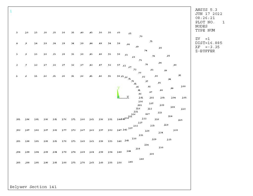
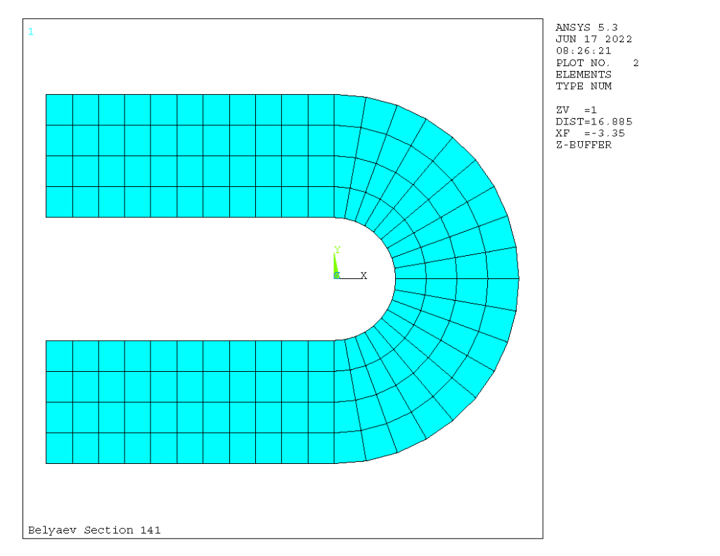
One thing that would have made the model smaller was to use symmetry by splitting the model at the midpoint of the curved beam section. Since the model is simple, this was not done, and it makes for better illustration of the results. Because we weren’t given the actual taper of the region to the left of the curved beam, we left it straight.


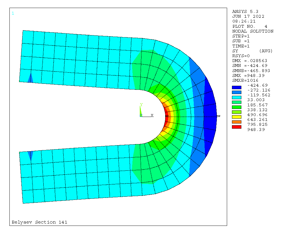
Of greatest interest in comparison to the curved beam analysis are the y-axis stresses. They are the greatest at the midpoint of the curved beam, as one would expect. It is also possible to see the points where the force is applied on the left side of the part. The shear stresses at this point are zero, as one would also expect, which means that the x and y stresses are the principal stresses at that plane.
The results show maximum and minimum stresses of +948 and -425 kgf/cm2, which compare favourably to the analytic curved beam solution. ANSYS also gives estimates of the maximum stress based on the error that might be generated by the discretisation error inherent in finite element analyses, and these stresses are +1016 and –466 kgf/cm2. A finer mesh probably would have resulted in both of these results coming closer to the analytic solution.
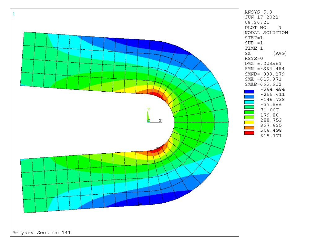
In order to see whether the x-axis and xy-shear stresses would produce a maximum of their own, we also ran a “stress intensity” analysis which shows the results which are used to compare to the yield stress and predict plastic failure. That result is below; it confirms that the stresses at the mid-point of the beam curve are in fact the maxima.

Vulcan Iron Works used finite element solid modelling primarily to analyse their offshore pipe caps. Vulcan Foundation Equipment, however, has used it in a way more like what you see above to design leader connectors.


3 thoughts on “Comparing Curved Beam Analytic Analysis with Finite Element Results”