Welcome to vulcanhammer.info, the site about Vulcan Iron Works, which manufactured the durable air/steam line of pile driving equipment for more than a century. Many of its products are still in service today, providing reliable performance all over the world. There’s a lot here, use the search box below if you’re having trouble finding something. Also look at the end of an article, there are helpful links to more information with every post.
Vulcan would have never endured as long as it did without a properly engineered product, especially in the punishing environment of impact pile driving equipment. There is a great deal of technical information on this site; here we give a glimpse as to how much of it came into being. There are special sections on CAD, Finite Element Analysis, and Numerical Analysis.
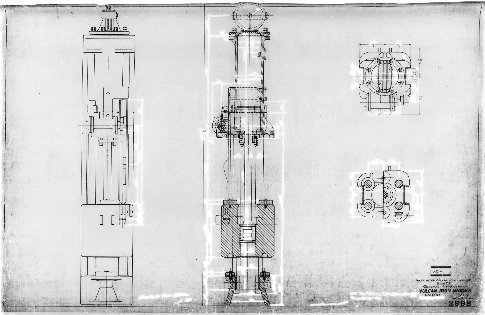
The first extant layout of the Vulcan #2 Hammer, dated 9 February 1887. It’s probably the first extant layout of the Warrington-Vulcan hammer. Until about World War I, it was common practice for Vulcan to lay out the general arrangement and then the shop produce the hammer from just that drawing. It’s an indication of both the skill and the decision making ability of those actually producing the product, and also probably of the involvement of those doing the design work.
Once the hammer was designed, leaders were necessary. This set of leaders is dated 11 April 1889 for O.H. Ernst, Major of Engineers, Galveston. As was the case for many years, this set was made out of wood. Leaders were made for both drop hammers and steam hammers. Other designs can be seen in our catalogue review. In the early years of the product line, American pile driving equipment of all kinds was generally run on a “dedicated” rig, i.e. one which was only used for pile driving. The practice of using a multi-purpose crane became standard around World War II. The dedicated rig remained popular outside the U.S. and has made recent inroads in the American market.
Any pile driving rig needs a “prime mover.” Many smaller ones used human or (more commonly) animal power. Vulcan built its reputation on steam driven equipment, and produced steam engines for some of its pile driving rigs. One of those is shown below. Note the rotary Corliss valve at the top of the drawing. This is the same type of valve that was used in the Warrington-Vulcan hammers and every other Vulcan hammer except for the #5, California series hammers, pile extractors and the Single-Compound hammer (the last two were valveless.)
the design of the valve, trip (cam) system and the steam chest was at the heart of every Vulcan hammer. Below is a layout of the “00” hammer dated 16 January 1912. Unfortunately that hammer size didn’t quite get off of the ground, and Vulcan would wait nearly twenty years before producing a hammer of that size.
Another, more elaborate view of a steam engine, here a pile driver hoisting engine, dating from 1903.
Vulcan’s reciprocating steam engines weren’t only used on pile driving rigs. In the same era Vulcan was also heavily involved in building dredges. We have a complete page on the subject; we’ll concentrate here on some of the design engineering aspects of those vessels.
A “strain sheet” for a truss design for the #3 dredge dated 20 February 1889. Using a combination of graphical and analytical techniques, the stresses and displacements in the truss are computed.
Another strain sheet, this time for the dipper friction, done by George Warrington and dated 22 April 1893.
From the beginning of the Warrington-Vulcan product line (and presumably earlier) until the 1950’s Vulcan drawings were largely drawn in India ink on linen. They were thus durable and reproduced well, and (as is evident here) have some artistic value. Unfortunately they were hard to change, but given the static quality of Vulcan’s product line that wasn’t as big of a disadvantage as one might think.
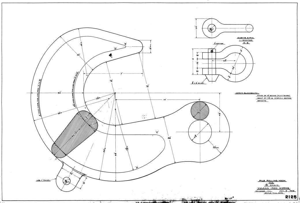
An example of Vulcan’s vertical integration: a pile hook, along with a shackle to go with it. Today components like this (especially the shackle) are usually purchased. On the right is a thoughtful “note to blacksmith.”
Although it’s hard to read, a “stress and force” diagram for leaders. The analysis of statics was well established in engineering education and practice by the last half of the nineteenth century and is employed in this case on pile hammer leaders. In this case the leaders are being analysed using a truss type of model and a graphical solution to the static equilibrium equations. Truss models are, strictly speaking, inapplicable to leaders, because the joints are not pinned, but can be a reasonable approximation. The labour of calculations pushed the industry towards a more “section modulus” approach (which has limitations of its own) but the best solution to date has been finite element analysis, which will be discussed below.
Another analysis with a more contemporary urgency is overturning of the rig. Below is an overturning analysis for a swivelling pile driver. Whether the rig is an old Vulcan rig, conventional crane rig, dedicated pile driving rig or an excavator mast mounted hammer, preventing overturning is essential.
Not all drawings were for sold product. Below is a diagram for modifying a planer to make a machine that would cut the cam on the ram of a DGH-900 hammer, from 1958. Today operations like this would be programmed into CNC machinery, but at the time the skill and ingenuity of the tool and die maker were applied to the task.
Between the World Wars Vulcan’s proficiency in ink and linen reached its height. Below is a general arrangement for the 1800 closed type hammer, drawn in 1931.
The hammers needed design and drawings, and so did the packaging. Below is an export box for the Vulcan #1 hammer. Vulcan was engaged in international commerce from the earliest days of the product line. Sometimes that was generated by American companies working overseas and sometimes by foreign concerns. For domestic shipment Vulcan usually mounted its hammers on skids, either wooden or steel. In more recent times the hammer was simply chained to the flatbed. For offshore hammers a steel skid was necessary, and the hammer was shipped as deck cargo.
Towards the end of the 1950’s Vulcan made two important changes in the way it made drawings: it went to pencil drawings and it drew them on vellum, which was preprinted with standard borders and title blocks. Additionally, after the move to Chattanooga it mandated the use of lettering templates. All of these resulted in drawings that were easy to change and had a more uniform look about them, but did not have the visual appeal of their earlier counterparts. Also, the vellum tended to fray with repeated reproduction; Vulcan’s reproduction machines used a contact process with ammonia development, which made the office stink, especially with poor ventilation. This forced frequently used drawings to have to be redrawn frequently.
Vulcan rectified many of the weaknesses of the pencil/vellum system around 1970 with two changes: it went to mylar drawings, which were expensive but lasted longer, and went from a plain graphite pencil to a “grease” pencil for darker lines and better reproduction. A nice example of this is the general arrangement of the 520 hammer, shown below, from 1982.
From 1967 to 1984 Vulcan had two engineering facilities: Chattanooga and West Palm Beach. Below is a sample of the latter’s output, which reflected its mission as a fabricating facility, primarily for Vulcan’s offshore leaders.
When it was time to go “back to the drawing board” at the Special Products Division, this is where they went: part of the engineering section of the Division, July 1974.
Below is an example of one of these, a layout of an ocean pile hammer from the late 1960’s.
The drawing board(s) in Chattanooga. On the wall are sheet pile sections, cut from actual sheet piling and used to lay out sheet pile caps. In front of the sheet piling are two draughtsmen who started at Vulcan in the early 1970’s. On the left is Michael Steven Alexander, who worked for Vulcan until he left during the downturn in the first part of the 1980’s. On the right is William C. Harrison, who went off the board to become Vulcan’s Field Service Representative in 1981.
Computer Aided Design (CAD)
By the mid-1980’s CAD was becoming a viable option for companies the size of Vulcan. In 1986 Vulcan purchased its first personal computer (PC) for the purpose, but the original software was unworkable, so Vulcan purchased DesignCAD and began producing drawings by computer drafting. The first hammer to be principally designed by CAD was the Vulcan 1400 vibratory hammer.
A screen shot from DesignCAD 4 for DOS, showing the hydraulic schematic for the Vulcan 2800 vibratory hammer. Given the limitations of DOS and the computers they ran on, the results that DesignCAD produced were amazing. Additionally DesignCAD did fine with just a keyboard, a mouse and a standard graphics card, obviating the need for additional hardware such as digitising pads.
By 1990 hand drawing (except for changes) was pretty much a thing of the past. Below is the general arrangement of the Vulcan 5110 hammer, the last new model to be placed into production by the Vulcan Iron Works.
While Vulcan’s competitors such as HBM trumpted their use of FEA for designing hammer components, Vulcan got its start in 1977 with the analysis of the 6250 pipe cap, which was being proposed to McDermott. The analyses were conducted by Dr. William Q. Gurley at the University of Tennessee at Chattanooga, who was later involved in this effort.
Element grid for the Vulcan 6250 pipe cap.
Displacement Diagram for the 6250 pipe cap.
Maximum shear stress diagram for the 6250 pipe cap.
Finite element analysis was revived in the 1990’s for the analysis of the leaders. Below is a sample of that effort, from 1996. In both cases the ANSYS software package was used.
Vulcan went on to analyse the 6300 pipe cap when McDermott “upsized” the hammer. Vulcan also conducted analyses on other hammer size pipe caps and piston rods as well; the former led to lightening the pipe caps considerably.
Numerical Analysis
For most of its history Vulcan used “closed form” solutions to predict the cycle behaviour of its hammers. In the early 1980’s, however, Vulcan developed the capability to analyse a hammer cycle using numerical methods and flow prediction, including valve losses. The first hammer to use this type of analysis in the actual original design of the hammer was the Single-Compound Hammer, where the complexities of the flow made such an analysis almost mandatory.
The “indicator card” developed for the S/C hammer, using an HP-85 computer, 1982. The output was actually printed on thermal tape. The HP-85, with its Basic programming and VisiCalc spreadsheet, was a useful device for hammer design and trade union negotiations alike.


Thanks for a great rread
LikeLike