
All fluid flow in Vulcan hammers is regulated and directed by a valve. For most Vulcan hammers (the California series being a notable exception, the #5 is another) the valve is a Corliss type valve modified from those used in steam engines. Simple and reliable, it, like any other valve, is subject to losses as the air or steam passes through it. These are reflected in the mechanical efficiency of the hammer.
The losses due to air or steam flowing through the valve are generally not the most significant source of energy losses in a pile hammer. In the late 1970’s and early 1980’s, with the increase in sheer size of the hammers, these losses became of more concern. It was necessary to at least attempt to quantify these losses instead of using a “standard” back pressure value.
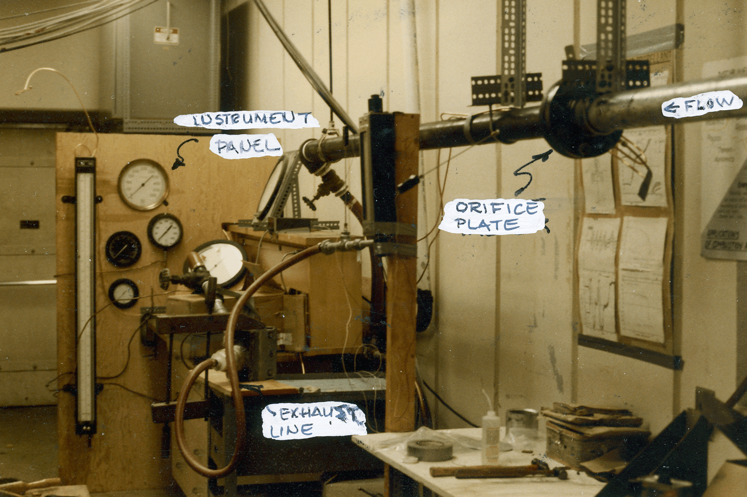
In May 1979 Vulcan contacted the Georgia Institute of Technology in Atlanta about using a Vulcan #1 series valve (like used in the #1, 06, etc.) in a test to determine the losses of air flowing through these valves. At this point a major problem was encountered: the air flow required to properly test the valve was too large for Georgia Tech’s equipment. Reaching out to Lockheed didn’t help either; they couldn’t do it. At this point Vulcan came up with an alternative: use the DGH-100 valve, which was a Corliss valve albeit much smaller, for the test. Making things easier was the fact that the DGH-100 used a small aluminium valve chest, which made the valve mounting simpler.
This proved feasible and Vulcan received a proposal from Brady R. Daniel at Georgia Tech for these tests. The valve was tested in two “configurations”:


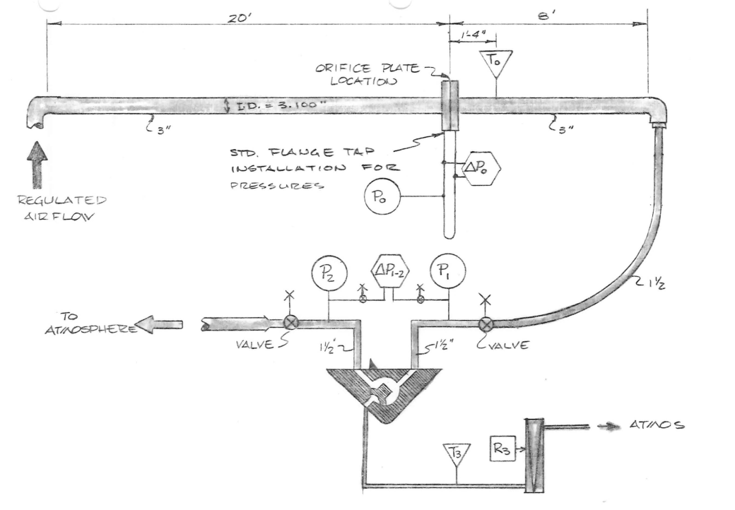


The tests were run and the report was presented in October 1980. The immediate results were as follows:
- The report showed that the valve could be modelled essentially as a sharp-edge orifice. In the context of incompressible fluids, this is explained here.
- A numerical method was developed to analyse the hammer cycle, as opposed to the closed-form solutions that had been used since the beginning of Vulcan pile hammers. This led to some design changes, and was also adapted for the Single-Compound hammer design.
The report also contained some suggestions for “streamlining” the design of the valve. These were not adopted, and the reason should be noted.
With the Corliss type valve, the Valve Port 1 is continuously pressurised, and this in turn forces the valve against the valve chest (or liner in the case of most newer Vulcan hammers.) With proper lubricant this seals the valve and further sealing (rings, seals, etc.) are unnecessary. This is a major reason why Vulcan hammers are as reliable as they are under the dire circumstances many operate. But that comes with a price. As with any design, there are trade-offs, and in this case the simplicity of the valve is traded off for efficiency. The simplest way to deal with this is to properly size the valve, and this was the main reason for the Valve Loss Study.
The Valve Loss Study is an interesting example of design analysis (others are here) which even an old product line like Vulcan’s can benefit from.


6 thoughts on “The Valve Loss Study”