

As was the case with the previous post Tapered Keys and Their Use In Vulcan Hammers, the topic of interference fits between machined parts doesn’t get that much coverage these days. In spite of that it’s an important part of machine design in general and Vulcan in particular, especially with the ram points. Before we get into what a ram point is an overview of the theory is a good place to start. As was also the case with the last post we will use William Ledyard Cathcart’s Machine Design, Part I: Fastenings. The theory behind this hasn’t changed much since the text was published in 1903, as can be confirmed by Timoshenko (1956) and Belyaev.
The Basics
The whole business of the stresses and pressures induced by interference fits comes from the stresses in thick walled cylinders, and the theory is explained by Cathcart below.

If you look at Figures 2 and 3 in the upper left hand corner, you will see two pistons A pressurising the fluid to a pressure P0. The pressure induces a radial pressure p and a circumferential (hoop) stress t in the cylinder, both of which change with the radius of a point o. Although pressure vessels are certainly governed by this theory (and the thin-wall simplification) a major interest for naval architects and engineers was artillery, a topic that is certainly relevant today.
Interference fits are an extension of this theory. Instead of a fluid, the initial overlap between an interior member and an exterior member induces a similar type of pressure in the outer member and also in the inner member. Cathcart explains this this as follows.

There’s a lot to unpack here, and we’ll use the Vulcan ram point as an example. One thing worth noting is that Figure 4 (which suspiciously looks like a Vulcan ram point) shows a solid shaft. The theory can also be extended to hollow shafts, which is discussed in Timoshenko (1956). One thing that Cathcart discusses that gets lost in later texts is the interference force between the shaft and the ring; this will be important in our discussion of ram points.
Vulcan Ram Points

The ram point is the “business end” of the hammer. You can see the point itself in the photo to the right; it’s the flat place at the bottom of the protrusion from the ram block (with a big chunk taken out by use.) That’s where the ram impacts the cushion material and from there the pile.
The earliest Warrington-Vulcan hammers used an integrally cast point, as is shown at the right. Around 1910 it became evident that this wasn’t going to work well, so Vulcan replaced it with an inserted steel point into a cast iron ram. (It has taken a while for this to propagate across the installed base; the ram at the right had been in service for about a century when its integral point was replaced.)
A diagram of the point, with installation technique, is shown below.
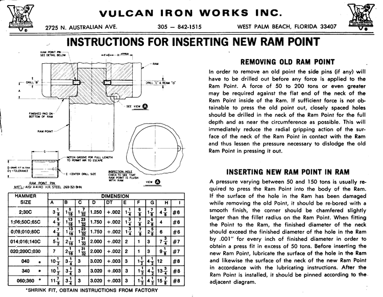

The point itself is the “shaft” while the ram is the “ring.” The removal of the point assumed that the ram point was broken where the small and large diameters of the point met, which was usually the case.
Let’s begin by restating Equations (64, C) and (38, C) for S1 and S2 as follows:


It’s important to keep the provision for different ram and ram point materials. Vulcan always used a steel ram point but sometimes the ram was cast iron and sometimes it was steel.
Now let us consider 

Now we turn to the ratio 

The shank diameter of the ram is 12 1/4″. The “ring” thickness is governed by the column bore pockets and is approximately 8 3/8″. Thus
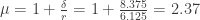
The ram is steel, so 


Getting Points In and Out
The ram and ram point together were intended to work as a single part; thus, their assembly and disassembly were not simple. Inserting a ram point is a tricky operation for new and used hammer alike, as is getting the stump out after breakage.
Restating Equation (62, C), the maximum forcing pressure (in or out) is given by the equation

where
- $latex Q = force to press in or out the ram point
coefficient of friction
diameter of the shank or stump of the ram point
length of shrink fit area between ram and ram point
Getting back to the Conmaco 300 hammer in question, 

Obviously the key variable is the coefficient of friction 
| Material Combination | f, dry | f, lubricated |
| Steel/Steel | 0.8 | 0.2 |
| Steel/Cast Iron | 0.5 | 0.1 |
The Conmaco 300 ram point would thus require a 1886 ton force unlubricated and a 471 ton force lubricated to either insert or remove the point. (Had the 300’s ram been cast iron, the two would have been 1179 and 236 tons respectively.)
The ram point removal instructions state the following:
A force of 50 to 200 tons or even greater may be required against the flat end of the neck of the ram point inside of the Ram. If sufficient force is not obtainable to press the old point out, closely spaced holes should be drilled in the neck of the Ram Point for the full depth and as near the circumference as possible. This will immediately reduce the radial gripping action of the surface of the neck of the Ram Point in contact with the Ram and thus lessen the pressure necessary to dislodge the old Ram Point in pressing it out.
The truth of these can easily be seen in the calculations. To put one back in the ram (or to do so the first time) the following is stated:
A pressure varying between 50 and 150 tons is usually required to press the Ram Point into the body of the Ram.
It’s worth noting that, the smaller the ram point, the smaller the force required to press the point in because the area is smaller (assuming the contact pressure is the same.) Another thing that may have worked in Vulcan’s favour was if the (more likely) ram experienced plastic deformation. It’s also worth noting that Vulcan stated the following:
The above press fit so far as tolerance is concerned is based upon the use of Molykote type G grease. To obtain satisfactory results in accordance with instructions do not use any other form of lubricant other than that specified.
The wisdom of this is also evident from the table, although in some cases it probably wasn’t enough. However, using grease had consequences. One of those was the use of ram point pins, which were the result of points occasionally coming out during use. The event was so rare that, when I first came to Vulcan in 1978, Vulcan’s senior field service representative, Jess Perry, asked me to take the points out. I did and never regretted it.
But another problem was looming, one reflected on the chart. The Conmaco 300 was about the largest hammer size range that Vulcan considered pressing points into; it’s worth noting that for larger hammers Vulcan recommended shrink fitting the points in by either a) cooling the point with liquid nitrogen or b) heating the ram with a blanket. Examples of both are shown below.

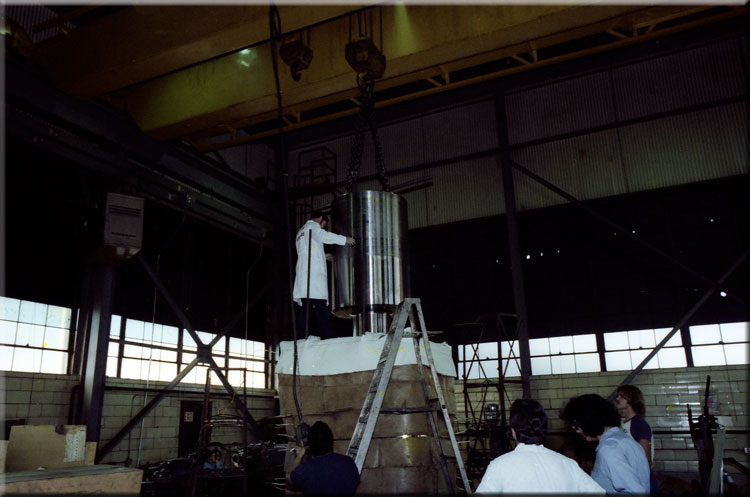
Installing a ram point into a ram in this way is a trickier operation than pressing it, for the same reason: misalignment invites the point to be hung in the ram before it seats into position.
Ram points are an interesting example of interference fits and also of the installation calculations that go with them.
Other Sources
- Timoshenko, S. (1956) Strength of Materials. Volume II, Third Edition. Princeton, NJ: D. Van Nostrand and Company.


2 thoughts on “Interference Fits and Vulcan Ram Points”