
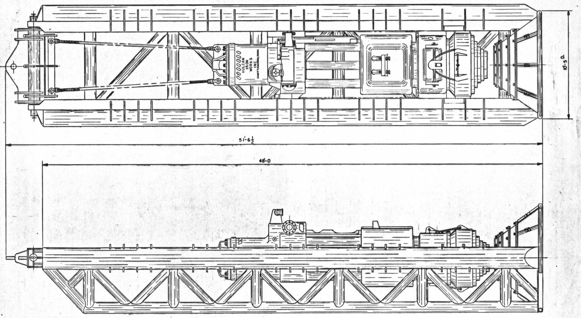
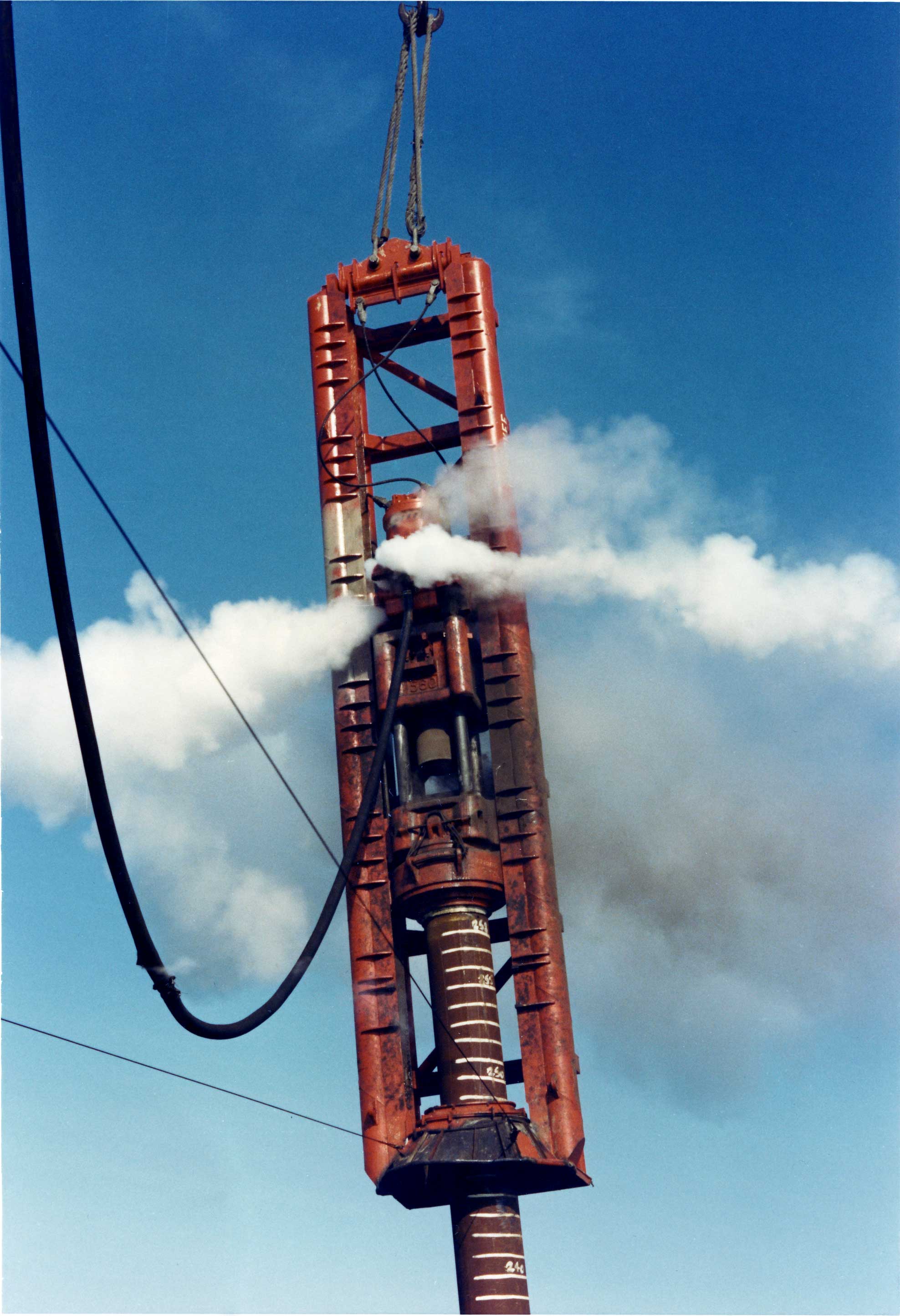
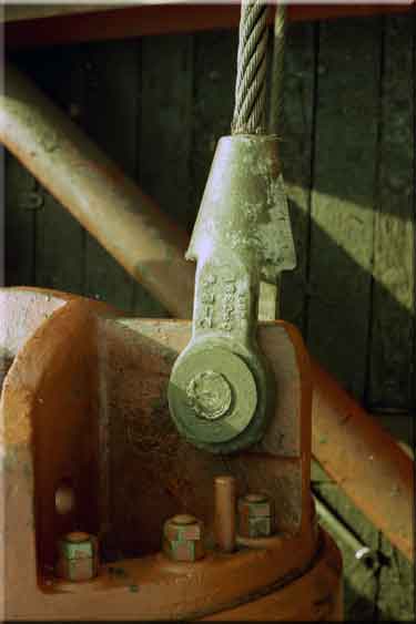
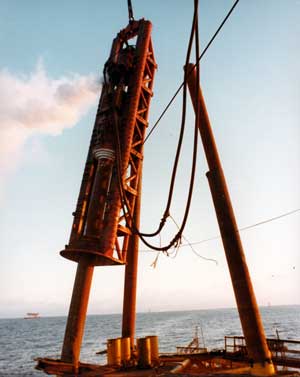
Any piece of construction equipment has to be picked up to be used, and picked up on a repeated basis. To do this requires lifting eyes, which in turn mate to either shackles or cable fittings. A good example of this from Vulcan’s product line can be seen above. You can see the two cables on the upper left extending from the leaders to the hammer. When the assembly is vertical, getting ready for operation, the cables prevent the hammer from falling through the conical stabbing bell at the right/bottom of the leaders. When the piles comes through that cone, the weight is relieved and the pile supports the hammer. At the end of driving the assembly is lifted and the weight goes back on the cables. (A more detailed description of this type of leader is here.) Some photos of this are below.
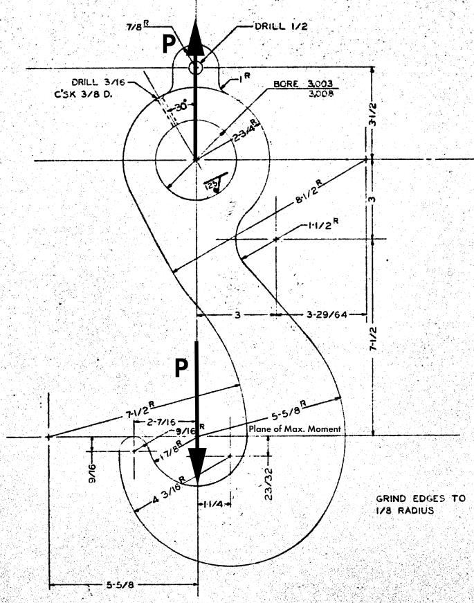
There are many other example of lifting eyes in the Vulcan product. For this presentation we’ll use the lifting hook from our discussion of curved beam analysis. In that analysis we concentrated on the lower part of the hook block; in this one we’ll concentrate on the upper one, but not exclusively.
Basics of Lifting Eye Design
In lifting eye design, there are four basic failure modes (Duerr (2008)):
- Tension in the net section;
- Splitting beyond the hole;
- Double plane shear, where the eye shears on either side of the hole to the top of the eye; and
- Dishing, which is due to the contact stress between the pin and the eye.
Duerr (2006) refers to curved beam stresses; the difference between curved beam stresses in a lifting eye and those of a hook is that you have two sets of bending, and the hole in the middle becomes a source of stress concentration, whose theory is related to curved beam theory.
Generally lifting eyes are design to a code such as ASME BTH-1-2005, which takes all of this into account along with such things as off-angle loads, different shapes of the lifting eye, etc. Sometimes it’s useful to use a spreadsheet such as this to apply these requirements. Our purpose here is not to present a comprehensive design technique but to explore some of the underlying theory behind the design of these critical parts.
Contact Stresses
Contact stresses take place when two bodies touch each other with an applied force. The best known type of contact stress (and one where the theory got started by Hertz) is when one sphere touches another, creating a point load. Elastic deflection then deforms both bodies and you have an area of contact. In this case we are dealing with two cylinders in contact with each other. If the cylinders are parallel (which these are) a rectangular contact shape will emerge between the parts.
The equations to compute both the maximum compressive stress and the width of the contact area for parallel cylinders are (Juvinall (1967))


where
and
- po = maximum contact pressure between the bodies
- b = elastic contact width of the bodies
- P = load between the bodies
- R1, R2 = small and large diameters (respectively) of the two cylinders. If the large cylinder is concave relative to the small one (as is the case here) R2 is negative
- L = length of contact
- E1, E2 = Young’s Modulus for the small and large diameters respectively.
- ν1, ν2 = Poisson’s Ratio for the small and large diameters respectively.
Examination of these equations show that, if the two radii are the same, the contact stress is zero, and is simply the bearing stress between the pin and the plate. Examination of the drawing shows that the upper hole is machined to some precision, which means that this is close to being the case. This is why it is important for the pin and the hole of the lifting eye to be as close as possible in diameter/radius.
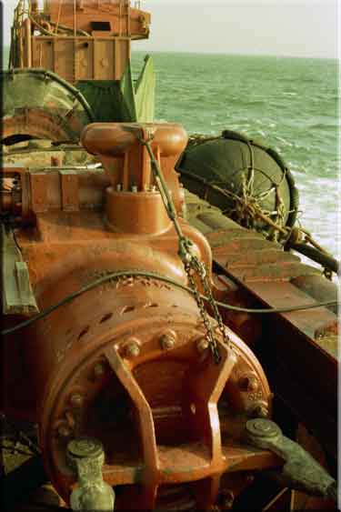
This is not always practical or possible. Looking at the photos above, the hole on the hammer is “as cast,” which is not very precise. On the leaders the holes were burnt out, which is a more precise process now than it was when Vulcan was active offshore in the 1960’s through the 1990’s. However, it is necessary to leave clearance for easy installation in the field.
Let us consider the example at the other end of the hook block above, where the hook goes around the pin to pull it up. The pin is 3″ in diameter, or R1 = 1.5″. From the drawing the hook radius at the point of pin contact is R2 = -1.875″. The other variables are as follows:
- P = 124 kips
- L = 4″ (plate thickness)
- E1, E2 = 30,000 ksi (both steel)
- ν1, ν2 = 0.3 (both steel)
Substituting these into the equations above yield a po = 147 ksi and b = 0.004″. As was the case with the bending stresses, the contact stresses are excessive; cutting the load in half would decrease the stress to 104 ksi, which is better but not ideal.
Observations About Contact Stresses and Lifting Eye Design
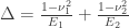
- For lifting eyes such as Vulcan used, the deflection generally isn’t a major consideration. It comes into play with more precise applications, one of which we will discuss below.
- Applications such as offshore leaders and other lifting points on the hammer weren’t the only ones in the Vulcan product line this type of theory applied to. An important one is the ram-column interface, which is critical to the proper operation of Warrington-Vulcan and Super-Vulcan hammers.
- All of this theory assumes the material remains elastic and in place. Placing the material into yield may actually help because it allows the load to be spread out to a larger area (larger b) and thus reduce the stresses. With the columns, once they have worn a bit (break-in) the contact area increases and the contact stresses are reduced. Getting to that point could be a chore with newer hammers, especially with offshore hammers such as the 040; the reason why grinding worked was that it increased the effective radius of the column and in doing so decreased the stress and increased the contact width. (Another problem with those hammers was the lubricant being used at the time. Traditionally Vulcan specified the use of grease. In addition to actual application sometimes lacking, grease did not stick to the columns offshore the way it should have. In the late 1970’s Vulcan transitioned to recommending an open gear lubricant, which has improved things dramatically.)
- Lifting eyes should be designed with the shackle or fitting the designer has in mind to be used with the eye. In many cases a reasonable design can be obtain by simply using the shackle or fitting to size the pin, thickness and outside diameter of the eye. Obviously this should be checked to make sure it works.
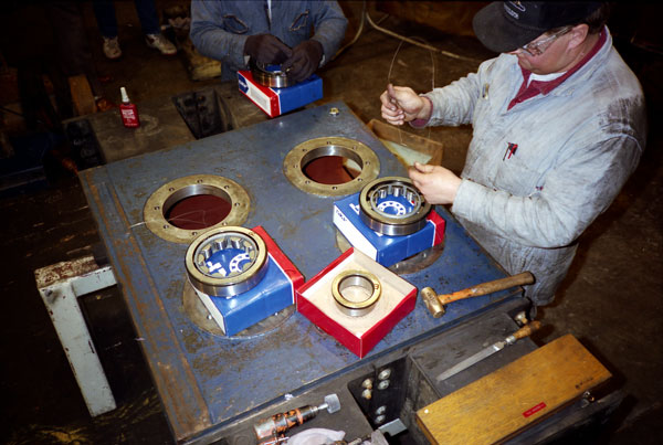
- The complexity of the problem expands with the inclusion of rolling contact and movement of the cylinders. That took place with Vulcan’s vibratory hammers, where cylindrical bearings were used (because of their greater load capacity.) Fortunately Vulcan did not have to deal with the design of the bearings themselves, but left that to the bearing manufacturer.
Applying Curved Beam Theory
The application of the curved beam theory to the top of the hook is the same as the bottom except for the following:
- The load acts on both side of the hole and not just the one, so it’s necessary to split the load to 62 kips on each side, since it’s symmetric both sides can be analysed in the same way. So P = 62 kips.
- R1 = 2 3/4″
- R2 = 1 1/2″
- R0 = (2 3/4″ + 1 1/2″)/2 = 2 1/8″
- t = 4″
- h = 2 3/4″ – 1 1/2″ = 1 1/4″
Making the same substitutions yields the inside tensile stress of 169 ksi and the outside compressive stress of -93 ksi. These are even higher than those at the hook; the lifting eye obviously needs to have its O.D. increased, even if the load is substantially decreased.
References
- Juvinall, R.C. (1967) Stress, Strain and Strength. New York: McGraw-Hill Book Company.
- Duerr, D. (2006) “Pinned Connection Strength and Behavior.” Journal of Structural Engineering, American Society of Civil Engineers, 132(2), pp. 182-194, February.
- Duerr, D. (2008) “ASME BTH-1 Pinned Connection Diagram Provisions.” Practice Periodical on Structural Design and Construction, American Society of Civil Engineers, 13(2), pp. 53-58, May.

