
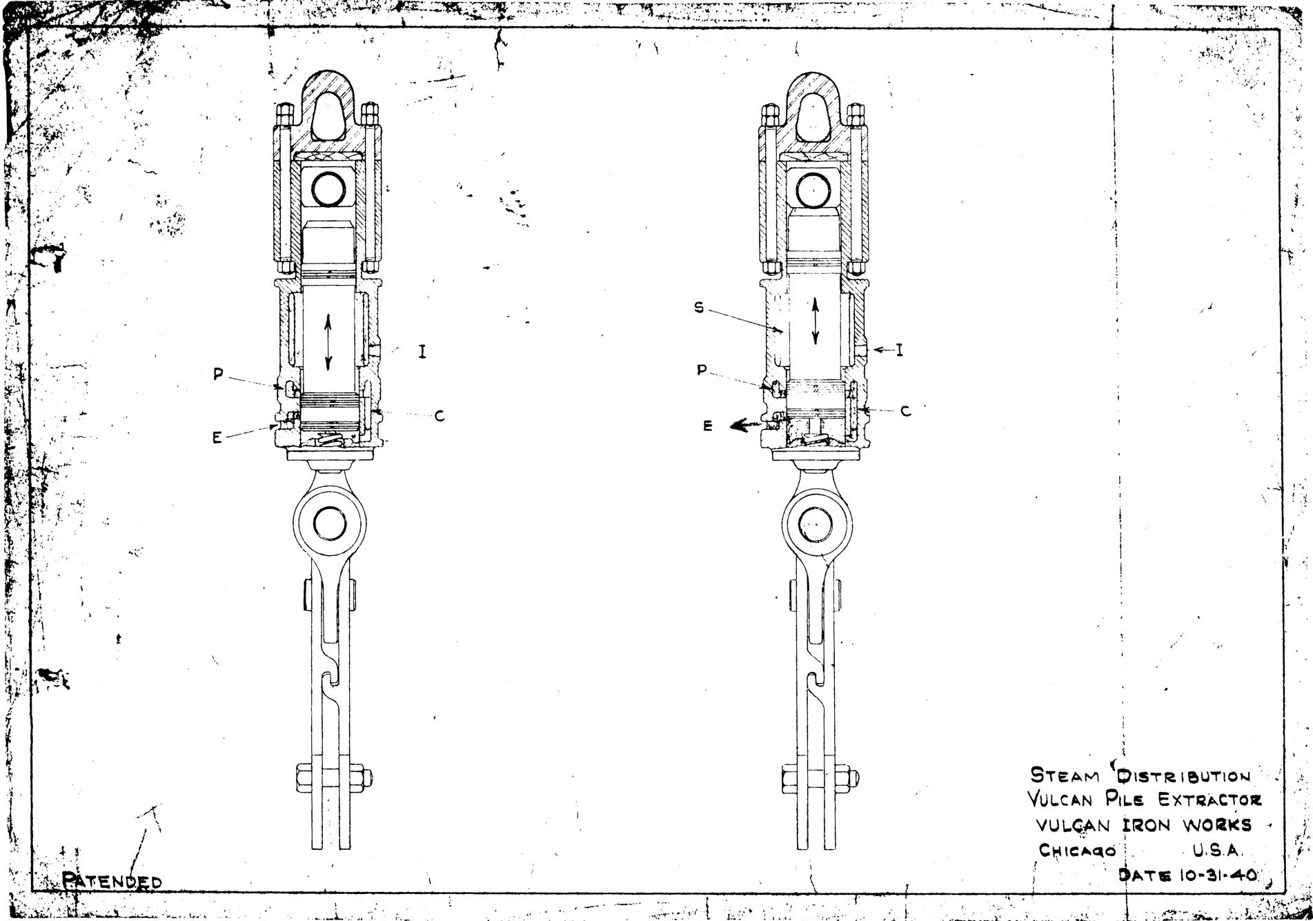
Vulcan was generally not hesitant to include information on the cycle workings of its air/steam hammers, but for some reason never included similar information on its extractors. Above is a diagram from 1940 which shows how this is done.
Basically we start with the view on the left. Air or steam is admitted through inlet I and is passed through chamber C to the area below the piston. The ram rises, since the large area at the ram bottom is pressurized. During the ram rise/upstroke the middle piston rings close off chamber C (right view) and port P and the ram rises by the expansion of the air or steam below the ram. The ram hits the anvil at the top of the stroke, which through the side bars jerks up whatever is attached to the extractor at the bottom. Towards the top of the stroke the air or steam under the piston is exhausted through E, the ram comes to the bottom of the stroke, and the cycle begins again.
The drawing above shows a coil spring at the bottom of the stroke to soften the impact of the ram to the bottom of the extractor. Later Vulcan extractors used a rubber spring and conversion from one to another is shown here.
The extractor’s cycle anticipated the Single-Compound hammer by its expansive use of air. Specifications on Vulcan extractors can be found here.


One thought on “How Vulcan Extractors Work”