

Most of our fluid mechanics offerings are on our companion site, Chet Aero Marine. This topic, and the way we plan to treat it, is so intertwined with the history of Vulcan’s product line that we’re posting it here. Hopefully it will be useful in understanding both. It’s a offshoot of Vulcan’s valve loss study in the late 1970’s and early 1980’s, and it led to an important decision in that effort. The theory was presented to us by Brady R. “Bob” Daniel, Senior Research Engineer at the Georgia Institute of Technology, who performed the valve loss study and who in turn drew it from Fluid Meters; Their Theory an Application, 5th Edition, The American Society of Mechanical Engineers, 1959.
Basics of Compressible Flow Through Nozzles and Other Orifices
The basics of incompressible flow through nozzles, and the losses that take place, is discussed here in detail. The first complicating factor when adding compressibility is the density change in the fluid. For this study we will consider only ideal gases.
Consider a simple orifice configuration such as is shown below.
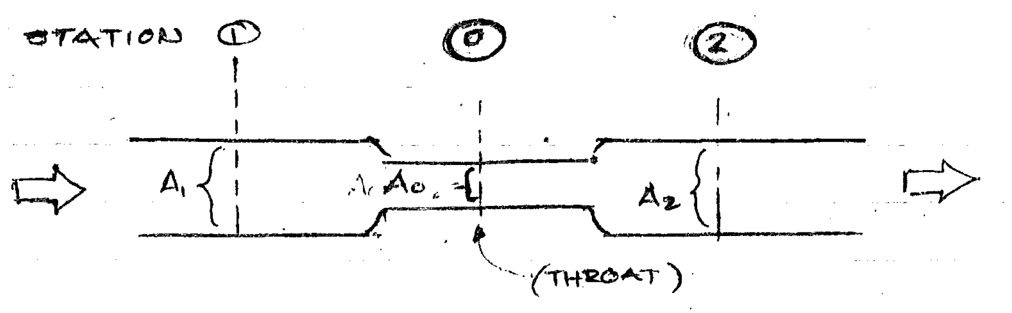
Fluid (in this case air) flows from the higher pressure to the lower one. The upstream point is 1 (A1, p1) and the downstream point is 2 (A2, p2.) In the middle is the valve at the throat (A0, p0.) In all cases A1 > A0 and A2 > A0. Where the flow reverses itself which point is upstream and which point is downstream changes, which is very significant.
The mass flow through this system for an ideal gas is given by the equation
(1)
where
mass flow rate,
throat area of orifice,
coefficient of discharge
upstream density,
upstream pressure, psfa
downstream pressure, psfa
gravitational constant
ideal gas constant or ratio of specific heats
for air
gas constant
upstream absolute temperature


This equation appears in many texts on basic fluid mechanics; however, there are two important changes which need to be noted.
The first is the inclusion of the coefficient of discharge. As the ASME source notes, “Critical flow through an orifice is complicated by jet area contraction. To compensate for friction losses, (Equation (1)) is multiplied by a correction factor called the discharge coefficient, CD.” In this article the coefficient of discharge 
The second is the inclusion of effects of upstream velocity, which is given by the square root term at the far right of Equation (1). If these effects are neglected Equation (1) reduces to
(2)
At this point is is worth noting that mass flow, although important for the study of valve performance, isn’t a very common way of expressing air flow in and out of Vulcan pile hammers. The most common way is standard cubic feet per minute (SCFM,) which is the volume of air per unit time of air at atmospheric pressure and temperature, subsequently compressed isentropically or adiabatically. Moving forward we will assume that the air properties inside of the cylinder are taken from free air at sea level during an ICAO “Standard Day” and compressed isentropically. This can vary depending upon the air compressor’s use of aftercoolers and, in past times, the use of the Vulcanaire Supertherm, but we will neglect these variances.
This means that the cylinder conditions for the exhaust case (cylinder is upstream) are computed by
(3)
and (for ideal gases)
(4)
For the case where air is admitted into the system and the cylinder is downstream, subscript 1 in Equations (3) and (4) is simply switched to subscript 2 for the downstream point and subscript 1 is retained for the upstream point.
Once these are applied to Equation (1), the SCFM is computed by
(5)
One final–and very important–restriction on these equations is the critical pressure, given by the equation
(6)
The critical pressure is the downstream pressure for a given upstream pressure below which the flow is “choked,” i.e., the volumetric flow rate will not increase no matter how much you either increase the upstream pressure or decrease the downstream pressure without further modification of the system. This limitation, which was observed by Saint-Venant, is due to achieving the velocity of sound with the flow through the nozzle or valve. A more common way of expressing this is to consider the critical pressure ratio, or
(7)
As you can see, this is strictly a function of the ideal gas constant. It’s certainly possible to get around this using a converging-diverging nozzle, but most nozzles, valves or orifices are not like this, and certainly not a Vulcan 06 valve. We now turn to the analysis of this valve as an example of these calculations.
Application: the Vulcan 06 Valve
The first thing we should note is that pile driving equipment (except that which is used underwater) is designed to operate at sea level. Using the standard day, free air has the following properties:
- Temperature: 518.67 °R
- Density:
- Pressure:
(or psfa)

Now let’s consider the valve for the 06 hammer (which is identical to the #1, 505, 306 and 506 hammer..) A valve setting diagram (with basic flow lines to show the flow) is shown below.

Note the references to steam. Until before World War II most of these hammers (along with most construction equipment) were run on steam. With its highly variable gas constant and ability to condense back to liquid, steam presented significant analysis challenges for the designers of heavy equipment during the last part of the nineteenth century and the early part of the twentieth. For our purposes we’ll stick with air.
There are two cases of interest:
- Intake: The left panel shows the air entering the hammer and passing through the valve to the cylinder. Pressurising the cylinder induces upward pressure on the piston and raises the ram. The valve position (which shows the inlet port barely cracked) is shown for setting purposes; in operation the valve was rotated more anti-clockwise, opening the inlet port.
- Exhaust: The centre panel shows exhaust, where air is allowed to escape from the cylinder. The piston is no longer pressurised and the ram falls to impact.
According to the vulcanhammer.info Guide to Pile Driving Equipment, the rated operating pressure for the Vulcan 06 at the hammer is 100 psig = 14,400 psfg = 16,516.22 psfa = 114.7 psia, or for simplicity’s sake 115 psia. The lowest pressure is the atmospheric pressure or 14.7 psia. The pressure ranges for the two cases are very different:
- Intake: For simplicity’s sake, we’ll use a constant upstream pressure of 115 psia. The downstream pressure is varied from zero to this value.
- Exhaust: It starts at 115 psia at the beginning of exhaust and will decline from there. The downstream pressure is constant 14.7 psia.
From this and the physical characteristics of the system, we can state the following properties:
- Upstream area for intake (from hammer geometry, approximate)
- Upstream area for exhaust (area under piston) = 0.927 ft2
- Throat area
- Coefficient of Discharge, assuming sharp-edge orifice conditions


At this point calculating the flow in the valve should be a straightforward application of the flow equations, but, as noted earlier there is one complicating factor: choked flow, which is predicted using the critical pressure ratio. For the case where 


- For the intake case, the minimum p2 = (.528)(115) = 60.75 psia.
- For the exhaust case, the maximum p1 = (14.7)/(.528) = 27.83 psia.
From an engineering standpoint the valve is a convergent nozzle. If we apply these limitations to Equations (1) and (5), the results are highly divergent.
Considering the intake case, the plot of downstream pressure vs. SCFM is shown below.
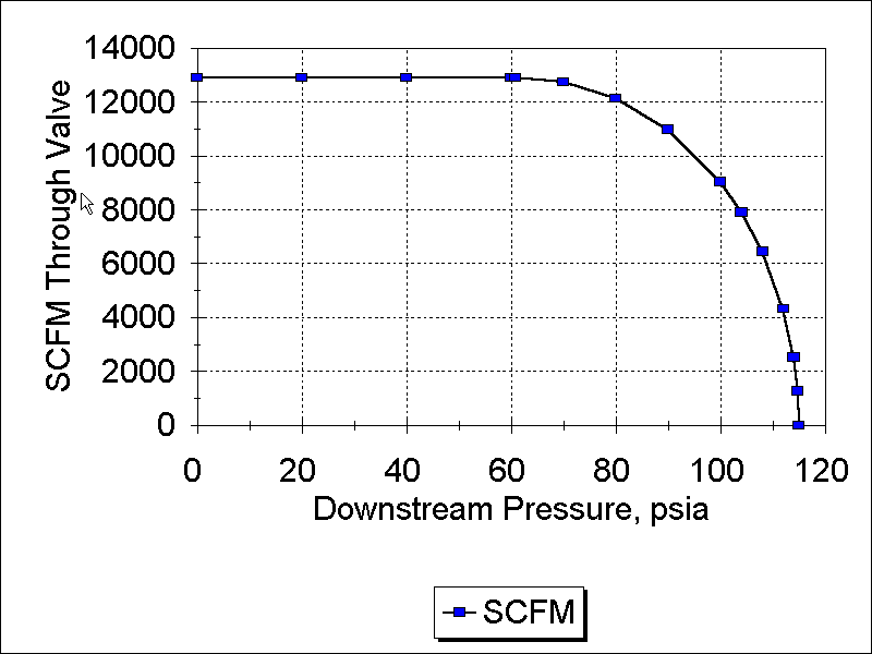
In this case we have the “classic” plot of this case: the flow is constant from zero until the downstream pressure reaches the critical pressure, after which the flow declines until it is zero when the two pressures are equal.
With the exhaust case, the situation looks entirely different, as shown in Figure 3.
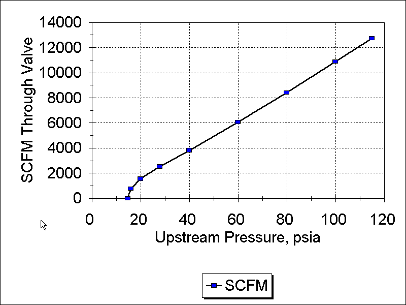
On first glance this seems to violate the whole concept of choked flow; the flow increases with increasing upstream pressure. However, we noted earlier that the volumetric flow is limited by sonic choking, which means that the throat velocity is limited by choking to the speed of sound. If the density of the upstream increases the mass passing through the throat at a constant velocity increases, and since the density of standard air is constant the volume of standard air will increase. Most elementary treatments of this topic are based on a constant upstream pressure, as we have with intake, and not a constant downstream pressure as we have here.
The airflow in the inlet case especially is substantial. It was this large volume of flow which prevented the use of the 06 valve (which could have been separated from the cylinder using a valve liner) in the valve loss study. The smaller DGH-100 valve was used instead.
It is interesting to note that the rated air consumption of the hammer is 625 cfm. This is much lower than the instantaneous critical flow. Although on the surface it seems inevitable that the hammer will “outrun” the compressor, as a further complication the hammer does not receive air on a continuous basis but on an intermittent one. For much of the stroke the compressor is “dead headed” and no air is admitted into the cylinder from the compressor. To properly operate such a device, a large receiver tank is needed to provide the flow when it is needed. The lack of such large tanks on modern compressors is a major challenge to the proper operation of air pile hammers.
Finally in every data point shown above the value of the denominator in Equation (1) is above 0.95 and nearly unity in many cases. This shows that the inlet velocity could in fact be neglected and Equation (2) be used in this case.


Reblogged this on Chet Aero Marine.
LikeLike