

The introduction to this series is here. The first installment of the calculations is here.
Calculations of Main Details (Strength
Calculations)
Strength calculations assume that the inertial forces during impact are 150 times those of the weight.
Rotor Shaft
We checked the rotor shaft strength in the optimal mode, i.e., when the impacting force direction formed a 90° angle with the direction of the blow. To simplify calculations consider that the forces act at one point. In the vertical place the shaft is loaded with impact inertia forces from the shaft weight and parts which are located on it.
where Q1 = inertial force from eccentric weight(s) and part of the shaft ahead of the eccentric.
Q2 = inertial force from the part of the shaft under the bearing.
Q3 = inertial force from the rotor weight and the middle part of the shaft.
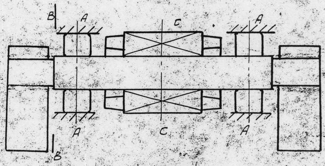
A diagram of the shaft assembly is shown below.
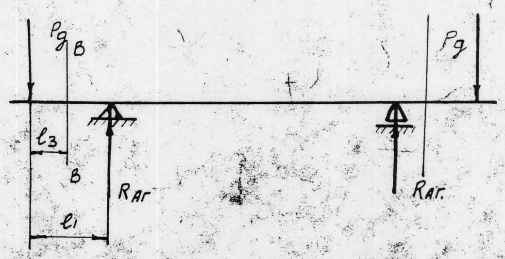
A diagram of the beam forces in the vertical plane is shown below.

A diagram of the beam forces in the horizontal plane is shown below.
The forces which act on the shaft in the horizontal plane arise from the vibrating forces of the eccentrics.
|
|
|
|
|
|
|
|
|
|
|
|
The reactions in the vertical plane are
![]()
The reactions in the horizontal plane are
![]()
The bending moment in the vertical plane in section A-A is
![]()
In section C-C it is
![]()
In section B-B it is
![]()
The bending moment in the horizontal plane in Sections A-A and C-C is
![]()
and for Section B-B
![]()
The sum of bending moments in Section A-A is
![]()
In Section C-C they are
![]()
and in Section B-B they are
![]()
The bending tension is calculated in the same way at all points.
![]()
For Section A-A
![]()
![]()
For Section B-B,
![]()
![]()
and Section C-C,
![]()
![]()
The tension in this section will be much less because the calculations do not take into account the force from the rotor shaft. Calculation of the shaft deflection will be done in Part C.
The calculations consider that the shaft is of uniform diameter, equal to 62 mm. In the vertical plane the deflection is equal to
![]()
where ![]() kg-cm
kg-cm
![]() = axial inertial moment of cross-section of the shaft
= axial inertial moment of cross-section of the shaft
![]()
E = spring modulus of shaft material = 2,000,000 kg/cm²
![]()
The deflection in the horizontal plane is equal to
![]()
The total deflection from horizontal and vertical moments is
![]()
In reality deflections will be smaller because we did not take into account the rotor forces.
Determination of Tensions in Vibrator Casing
The casing is subjected to loading tensions when the vibrator impacts on the pile cap. As the ram is located in the centre of the casing the critical sections are two perpendicular sections which are located at the planes of symmetry of the vibrator.
Let us determine the moment of resistance of the section which is shown in the drawing of bending tensions in this section, shown below.

This section is weakened by a hole for the ram but this weakness is compensated for by the local boss. So we do not take into account the hole and its boss.
The moment of inertia for the section relative to axis X-X is determined as
![]()
where ![]() = sum of inertial moments of the separate elements.
= sum of inertial moments of the separate elements.
![]() = sum of multiplication of squared distances from the mass centre of element ot the axis X-X by the area of the element.
= sum of multiplication of squared distances from the mass centre of element ot the axis X-X by the area of the element.
![]()
The moment of resistance for this section is
![]()
The distance between the axes of the electric motors is ![]() mm. So the bending moment is equal to
mm. So the bending moment is equal to
![]()
The bending tension is equal to
![]()
Let us determine the bending tensions in the section perpendicular to the axis of the rotors. The section is shown in the drawing below.

To simplify the calculations consider the section of the casing is symmetrical and consists of two circles and two rectangles.
The inertial moment is equal to
The moment of resistance equals to
![]()
Let us now determine the bending moment considering that the load from the weight along the axis parallel to the rotor axis is distributed uniformly.

![]()
The bending tension is equal to
![]()
Spring Deflection Calculation
The maximum force for which spring deflection is required is P = 1000 kgf. The number of spring N = 2. The maximum deformation of the springs is f = 200 mm. The load for each spring is
![]()
As the springs are operating in relatively easy (not hard) conditions we can consider the permissible tension equal to 5500 kgf/cm². So the permissible tension per 1 kgf of load is equal to
![]()
The necessary spring stiffness is equal to
![]()
So we choose the spring with the following specifications:
|
Average Diameter |
|
|
Wire Diameter |
|
|
Hardness of One (1) Turn |
|
|
Number of Working Turns |
Npad = 14.5 |
|
Total Number of Turns |
N = 21.5 |
|
Tension per 1 kgf of Load |
A = 11.18 |
|
Hardness of the whole spring |
|
So the spring we have chosen meets all of the requirements.
Determination of the Geometrical Configuration of the Eccentrics
Consider that the balanced part of the eccentrics (I and II; see diagram below) cancel each other.

So the coordinate of the center of mass of the rest of the eccentric (in the shape of a sector of a circle) is determined by the equation
![]()
![]()
The weight of the unbalanced part of the eccentric for a 1 cm thickness is equal to 1.7 kg. The eccentric moment of this eccentric is
![]()
The dynamic force of the eccentric is
![]()
The angular speed is ![]() rad/sec. The necessary eccentric moment of the eccentric is
rad/sec. The necessary eccentric moment of the eccentric is
![]()
The necessary total thickness of the eccentrics is
![]()
As during the determination of the eccentric moment it was increased a little, consider the thickness of the eccentrics equal to 80 mm.
This configuration of the eccentrics which we have come up with gives us an increase of its weight in comparison with the weight which is necessary to provide the required eccentric moment. So decreasing the moment of the rotary parts makes it easy to operate the motors.
Sizing the Bearings
The rotor shafts are mounted to spherical, double-row roller bearings No 3614 which have a coefficient of workability C = 330,000. The rotor weight Gb = 25 kgf. The eccentric weight is Gg = 28 kgf.
For the calculation of dynamic loads consider that the accelerations during impact are equal to 150 times the free weight.
As the shaft is symmetrical, each bearing is subjected to half the dynamic load
![]()
The shaft rotates at n = 950 RPM. Consider a factor of safety Kd = 1.5 and a dynamic load coefficient Kk = 1. The durability of the bearing “h” is determined as
![]()
Therefore, for 950 RPM, h = 160 hours.


6 thoughts on “Soviet S-834 Impact-Vibration Hammer: Calculations, Part II”