
In the last post Checking the Soviets: Determining the Bending Moment and Stress, and the Parallel Axis Theorem, we looked at a section which was represented to act as a beam. We learned that, if that’s true, then the way to reduce stresses isn’t just to add material, but to add it judiciously. In this section we’re going to look at the same piece from an angle 90 degrees from the previous one, but we’re going to challenge (in a crude way) the idea that it acts as a beam, and in a sense combine the two analyses.
Let’s start by looking at the simplified cross-section of the impact body below, as given in the post Soviet S-834 Impact-Vibration Hammer: Calculations, Part II:
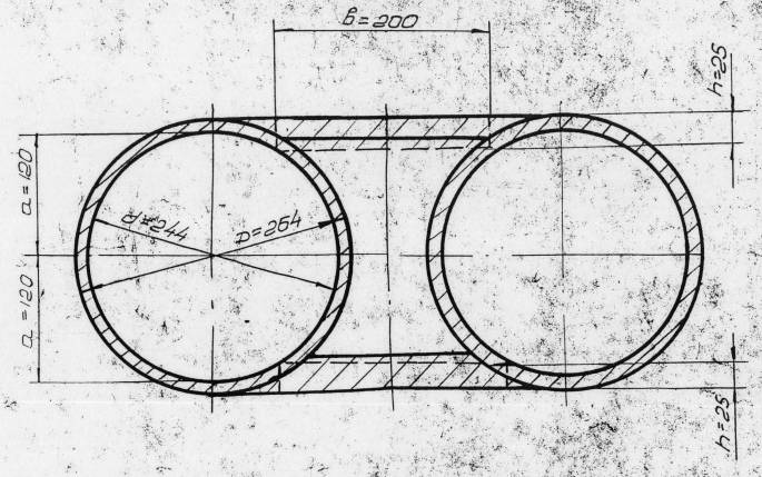
The two pieces which connect the “barrels” (where the electric motors and the eccentric shafts are) look like this when the centreline of the cross-section is cut and rotated:

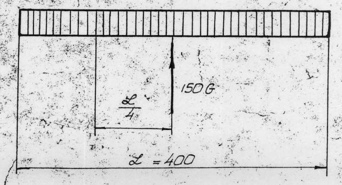
In any case, the cross-section is treated like a beam for this, where the load is uniformly distributed and the one support is the impact point at the centre:
Rather than once again replicate the analysis, we’ll start by challenging the assumption that it acts as a conventional beam. It’s simply too short (40 cm) and too deep (26.2 cm) even in the simplified form to be considered in this way. We’ll illustrate this by a somewhat crude finite element analysis using ANSYS. The element map is shown below:
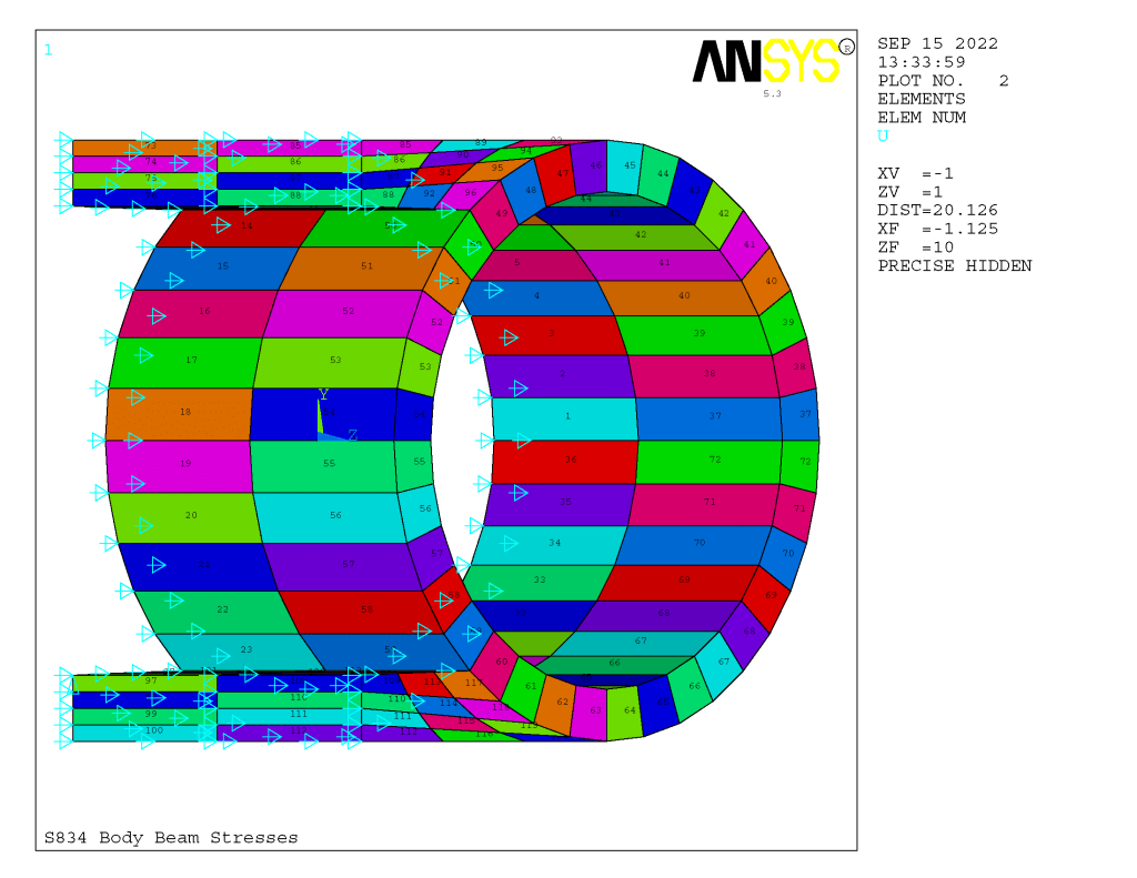
The elements are eight-node solid elements. The impact point is in the lower left hand corner of the model, and is modelled as a vertical restraint at one point (which is conservative.) The arrows represent symmetry nodes. The model is cut into quarters by applying symmetry at the two vertical planes (the x and z planes) which pass through the impact point. The z-axis runs through the centre of the “barrel,” and the y-axis is the only vertical axis for the model.
The nodal model is shown below, although it’s admittedly hard to read.
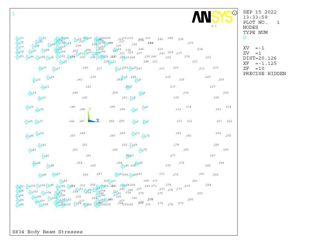
One thing ANSYS “complained” about was the shape of the nodes outside of the barrel. Without some other major revisions, this would have been hard to correct. ANSYS returned some significant discretisation errors which will be shown in the results.
Detailed information on the S-834 showed that the impact body weighed 210 kg, which means that a quarter section like we are analysing weights 52.5 kg. The model showed above, even when “beefed up,” only weighs 45 kg. Additionally the entire assembly with motors, shafts bearings, eccentrics, etc., weighs about 600 kg (according to the analysis,) and so each quarter should weigh 150 kg. To address this issue the remaining mass was added using point masses at the three nodes at the bottom inside diameter of the barrel.
The “beefing up” of the model from the original was justified by the additional information on the impact body and necessitated by the way the assembly was loaded. (That beefing up needs to be considered in view of the fact that the ribs described in the previous post wrap around the entire impact body.) Instead of adding external forces to simulate the loads, the acceleration of 150 g’s (discussed earlier) was applied to the entire model. In this way the loading was more realistically distributed in the model; the analysis is in reality a “pseudostatic” one.
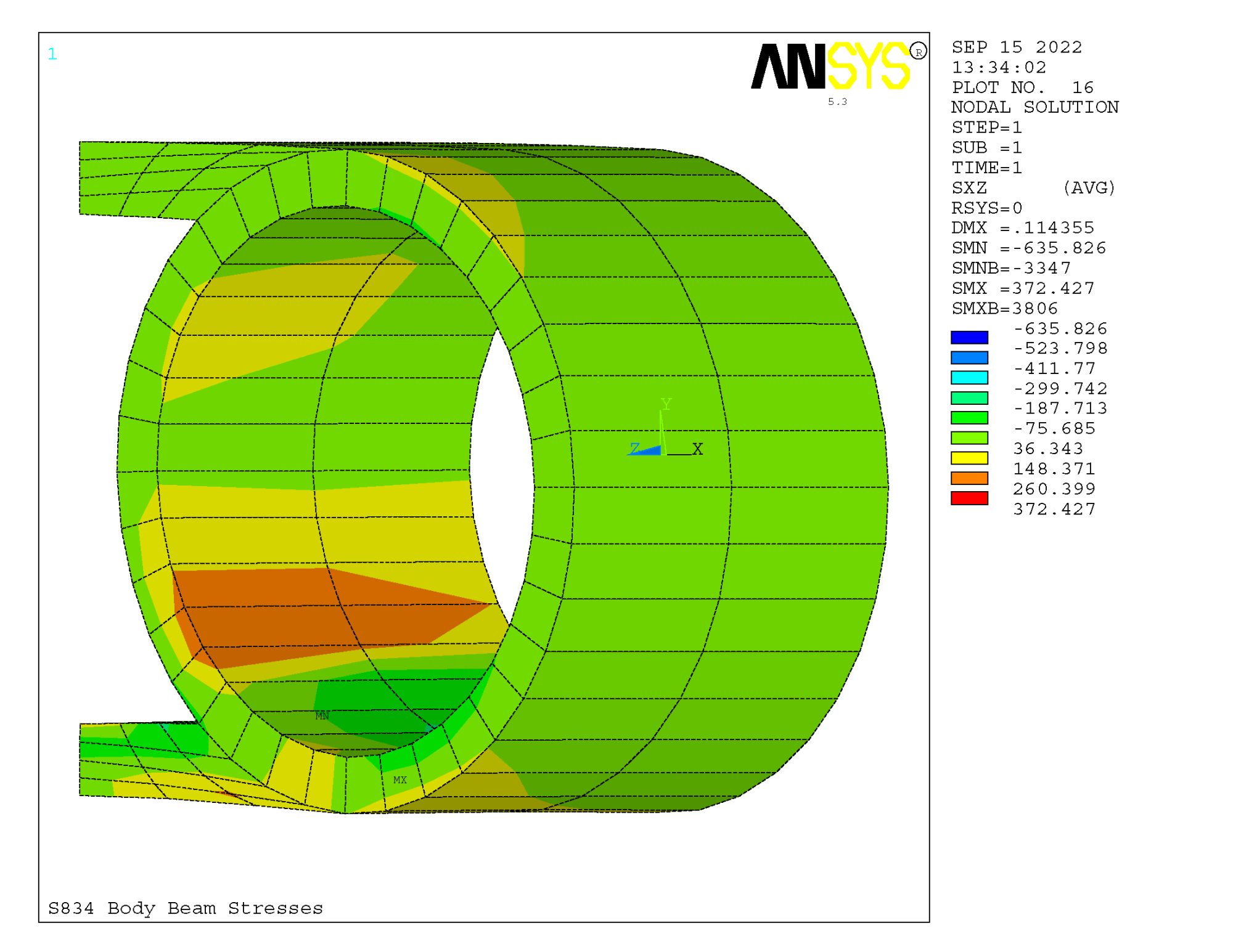
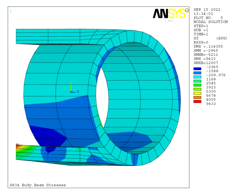
Applying this acceleration the results in the same orientation above are shown below for the stresses in all coordinate directions (normal in the x,y, and z, and shear in the xy, xz and yz,) the deflections and stress intensity results.


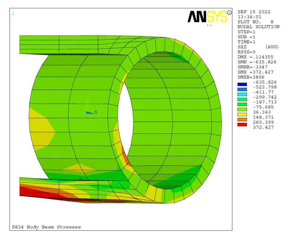


Rotating the orientation 90 degrees yields the following results:

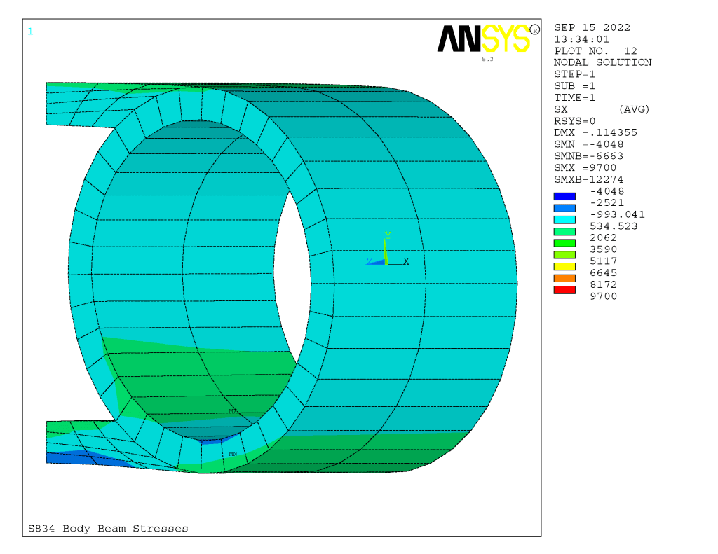
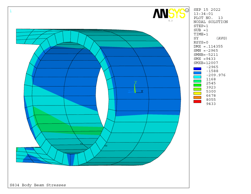
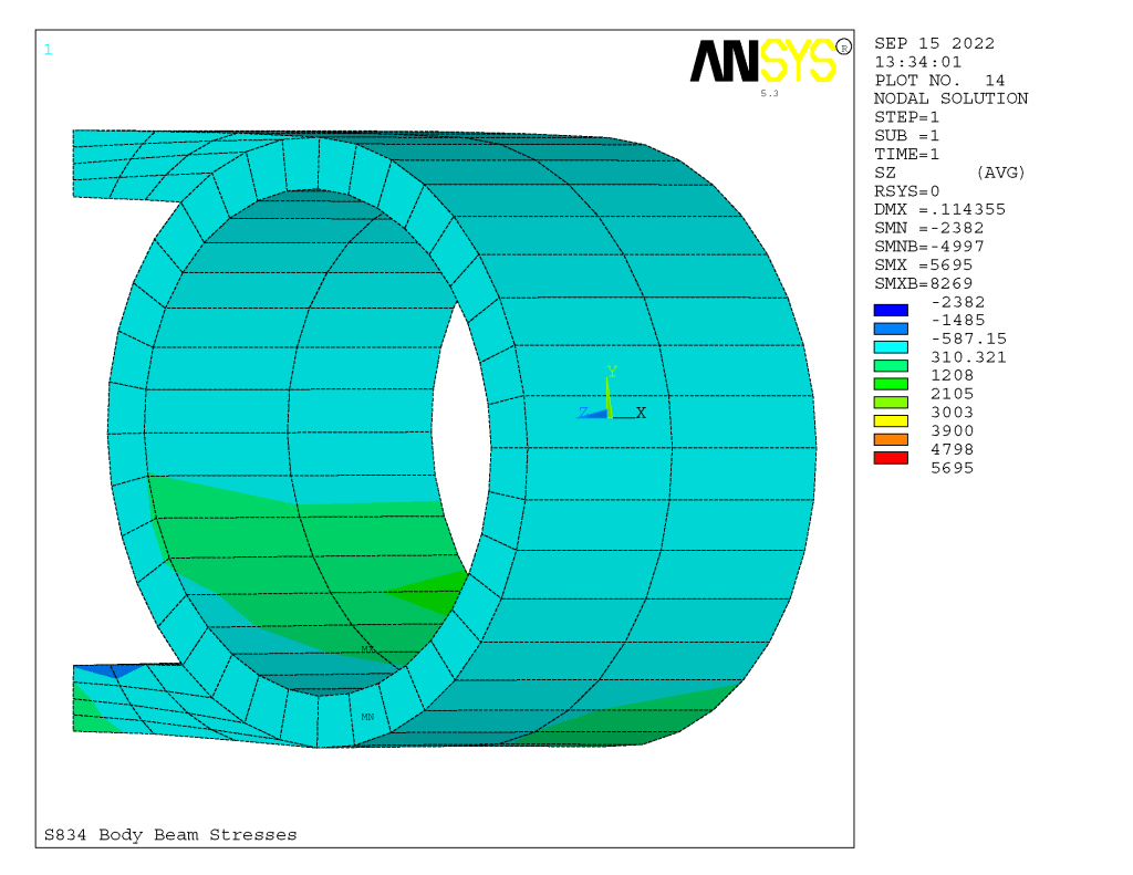


From these results we can deduce the following:
- The maximum deflection is 0.114 cm, which is not insignificant, especially considering the tight nature of the components that fit into the impact body and the fact that they occur nearly 500 times a minute during operation.
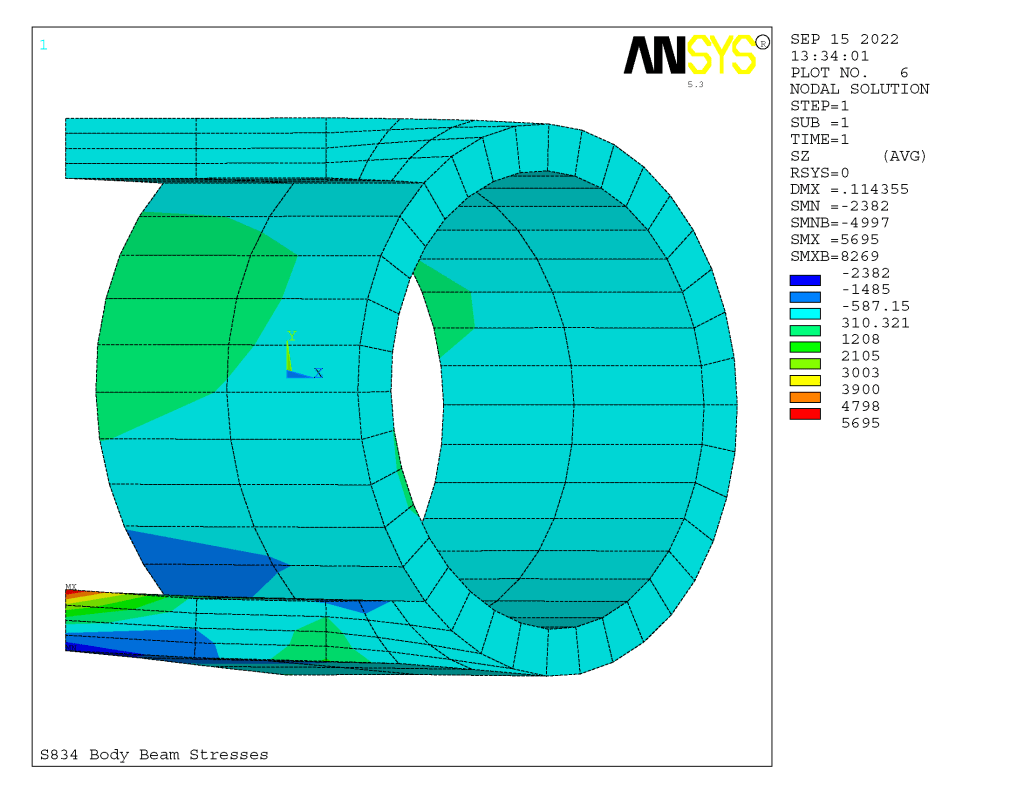
- Because of the unsatisfactory way the area outside of the barrel was discretised, ANSYS records a significant difference between the stresses the directly result from those in the model and those after its “correction” is applied. For example, the z-axis normal stress are estimated to vary from -2382 to 5695 kgf/cm2, but after correction they vary from -4997 to 8269 kgf/cm2. How significant this actually is could be cleared up by a rediscretisation of the model, but due to program limitations this is not practical.
- The maximum compressive stresses take place (as one would expect) at the impact point. The maximum tensile stresses take place directly above it in the lower “plate” which joins the barrels. What this means is that the lower plate is in reality the “beam” that transfers most of the load between the plates and not the two beams acting as one, as the previous post indicated.
- Except around the impact point, the stresses in the z direction did not increase very much, which calls into question the whole beam assumption of that part of the analysis.
- The original study computed the maximum stress in the x-axis as 435 kgf/cm2 and the z-axis as 220 kgf/cm2. The localised stresses were higher by several orders of magnitude.
Although the finite element study here is crude and subject to refinement, it shows that the application of simple structural theory to machine parts (especially those loaded in impact, vibration or in this case both) is subject to revision due to the different physical layout of the structural members.

