

The introduction to this series is here.
Moscow, 1963
Head of the Vibrating Machine Department L. Petrunkin
Head of Vibration Machine Construction: I. Friedman
Compiler: V. Morgailo and Krakinovskii
Specification
The impact-vibration hammer is intended for driving heavy sheet piles up to 30 cm in diameter as well as concrete piles 25 cm square up to a depth of 6 m for bridge supports and foundations.
|
Parameter |
Value |
|
Power N, kW |
9 |
|
Blows per Minute Z |
475 |
|
Revolutions per Minute |
950 |
|
Ram mass |
650 |
|
Force F, kgf |
5000 |
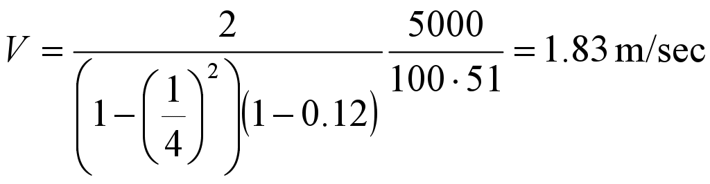
Determination of Velocity and Energy per Blow
Impact velocity is determined:

where
![]() = fraction of natural frequency (without limiter) to force
= fraction of natural frequency (without limiter) to force
frequency![]()
i = fraction of the number of revolutions to the number of impacts
R’= coefficient of velocity recovering (assume R’=0.12)
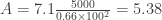
In our case

therefore

![]() rad/sec
rad/sec
![]() kgf-sec²/m
kgf-sec²/m
Energy of blow is determined as
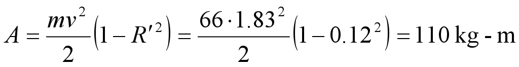
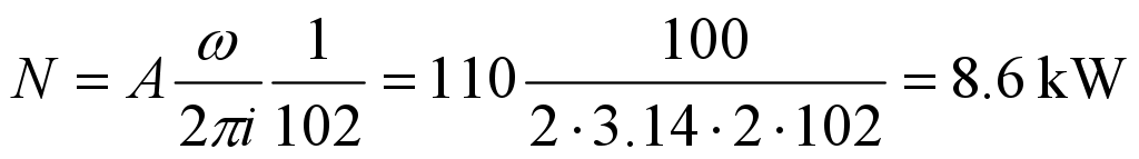
Power necessary to make impacts is
Impact-Vibration Hammer Springs
So that the impact-vibration hammer operates in the optimal mode while the gap is equal to zero, the spring suspension stiffness should meet the equation

where ![]() = stiffening coefficient = 1.1 to 1.3, assume 1.2
= stiffening coefficient = 1.1 to 1.3, assume 1.2

Stiffness Distribution and Maximum Deformations of Upper and Lower Springs
The upper springs are necessary to provide positive gaps, so their stiffness should be minimal to provide undisplaced operation the springs in the whole range of gap adjustment. Therefore

where Cb = stiffness of the upper springs
A = number of vibrations of the ram
a = maximum positive gap when the hammer is able to operate without danger of transferring into the impactless mode. When there is no limiter it is equal to the amplitude of vibrations

Assume a = 0.8.

where ![]() = coefficient which depends upon i and R’. Hammer coefficient of
= coefficient which depends upon i and R’. Hammer coefficient of
velocity recovery may be increased up to R’ = 0.2. In this case ![]() = 7.1.
= 7.1.
For calculation purposes let us assume A = 5.5. Now substitute the values into the formula

The bottom spring stiffness is then equal to

Now let us determine the maximum deformations. For upper and lower springs,


where b = negative gap. It is considered equal to “a” (maximum positive gap)
Assume ![]() .
.
Because of design considerations use four (4) upper and four (4) lower springs. The stiffness of one upper spring is

and the stiffness of one lower spring is

The material for the spring is “60 Sg” steel. The permissible tension in this steel is ![]() kgf/cm².
kgf/cm².
Upper Springs
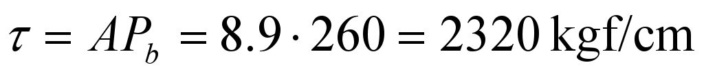
Tension per kgf of load is
According to the table of S.I. Lukowsky choose the spring as follows:

The stiffness of one turn ![]() and the number of working turns is
and the number of working turns is
Assume ![]() turns. For this spring,
turns. For this spring,![]() . The actual tensions in the spring are as follows:
. The actual tensions in the spring are as follows:
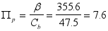
and the total number of turns is
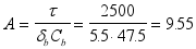
The full free height of the spring is

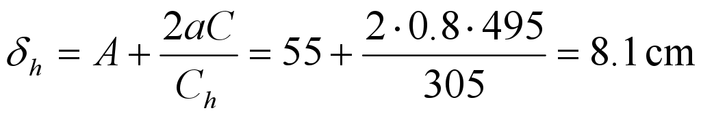
The distance between the support surfaces while the gap is equal to zero is

Lower Springs

According to the table the closest value A = 4.24 corresponds to the spring with dimensions

The stiffness of one turn is equal to ![]() . The number of working turns is
. The number of working turns is
Assume 10 turns.
The total number of turns is

The spring height in free position equals to


4 thoughts on “Soviet S-834 Impact-Vibration Hammer: Calculations, Part I”