
In our last post Checking the Soviets: The Strange Case of the Spring Constants we discovered some discrepancies in the design of the springs which, although essentially correct, were hard to explain given the information furnished. In this analysis an entirely different problem is encountered, one which is more familiar to practicing engineers.
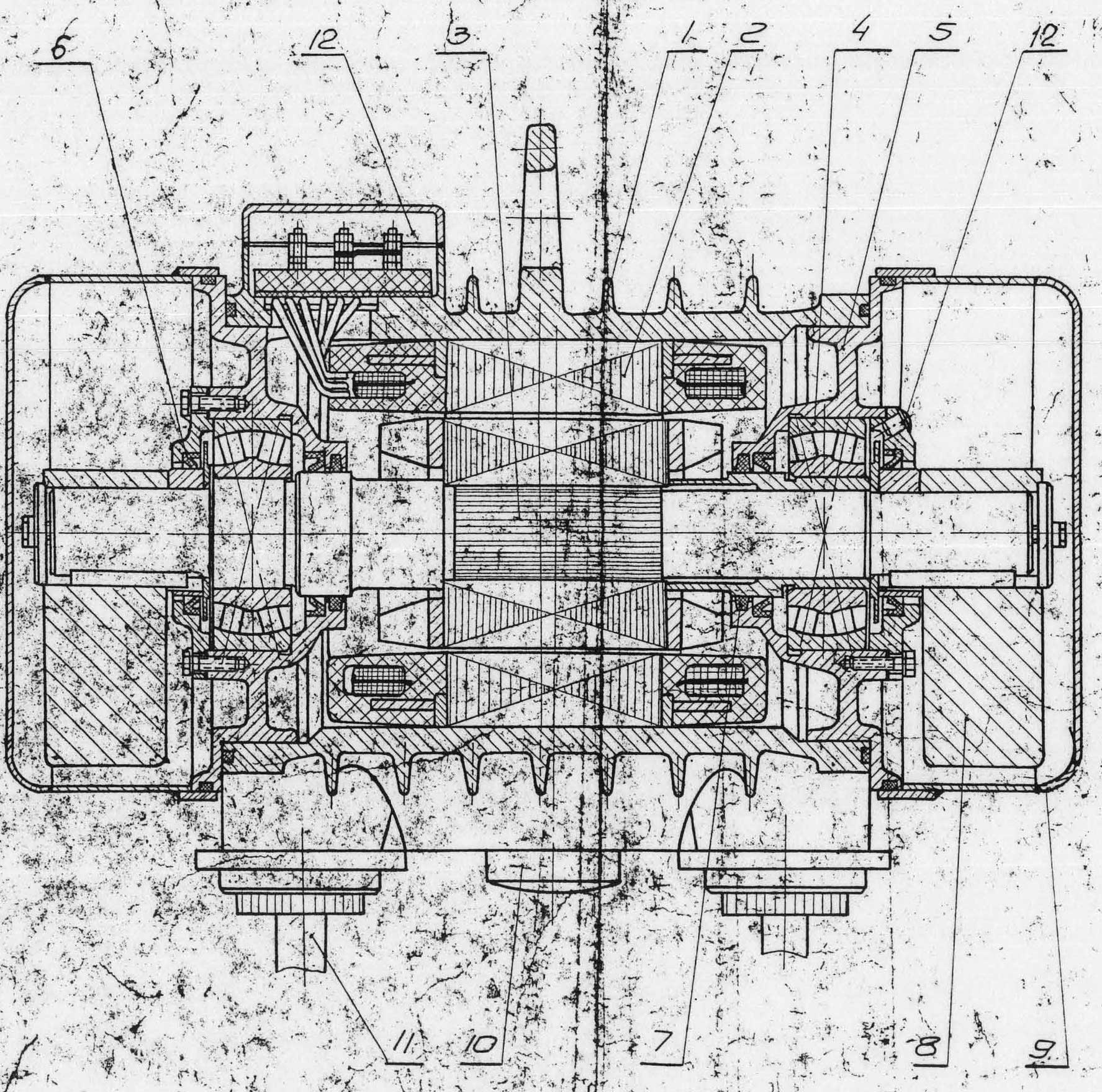
The problem at hand is the centre shaft where the electric motors in the middle drive the eccentrics on each end. We say “shaft” but in reality there are two of them side by side with four eccentrics total. A cutaway view is shown above. The centre shaft (3) is mounted between two bearings (4). The rotor for the electric motor is directly mounted to the shaft and is driven by the stator (2). The eccentrics (8) are mounted on each end. We thus have a true direct drive of the eccentrics in a way similar to that of the Uraga hammer which Vulcan marketed in the 1960’s.
The shaft is mounted from left to right. The left portion of the shaft which mates with the bearing is larger than the rest of the shaft; this necessitates the sleeve you see on the right bearing between the shaft and the bearing.
In their analysis of the bending of the shaft (given in Soviet S-834 Impact-Vibration Hammer: Calculations, Part II) the Soviets assumed two types of loading: the normal loading of the rotating eccentrics and the inertial loading of the impact of the “ram” on the anvil. The Soviets assumed a deceleration of 150 g’s. This is not unreasonable, especially for “steel on steel” impact, and is in line with the results of studies such as OTC 5395 Revisited: Analysis of Cushioned Pile Hammers and Concrete Pile Head Response to Impact. This reality is a major reason why designing durable impact pile driving equipment is such a challenge.
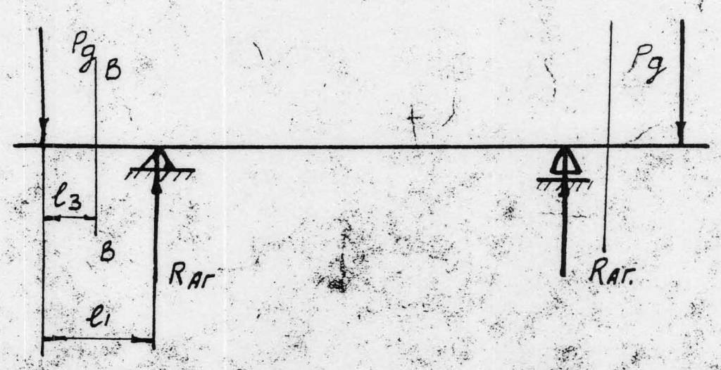
They also assumed that the two loads would be 90 degrees out from each other. They referred to the inertial loading as the “vertical loading” and the dynamic force of the eccentrics as the “horizontal loading.” The two loading cases are shown below, along with a diagram of the planes of interest. For simplicity they also assumed the shaft to be a uniform 6.2 cm in diameter.


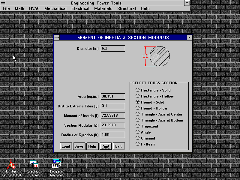
In checking their analysis we will make the same basic assumptions. To determine the bending properties of the shaft we used Engineering Power Tools in all its Windows 3.1 glory, ignoring the fact that the results are supposed to be in inches (any consistent units will do):
From here we employed the CFRAME program to analyze the beam/shaft. We have used CFRAME elsewhere; although old, it’s useful because it’s straightforward and also gives values for moments, shears and deflections all along the beam elements, which saves having to divide the beam up. The model is shown below.

There are only four elements, five nodes and two supports for this model. CFRAME allowed for the used of centimeters but not kilogram-force units; we were forced to convert the loads into Newtons, which was a minor inconvenience.
Having done that, the vertical load case (Load Case 1) is shown below.

The horizontal loads (Load Case 2) are shown below.

The resulting moment diagram for Load Case 1 is thus:
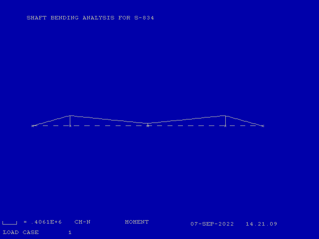
The maximum moment appears at the supports; it is 406,100 N-cm, which is in reasonable agreement with the (41400)(9.81) = 406,134 N-cm from the original hand calculations. The biggest discrepancy in moments appears at Node 3 (midway between the supports.) CFRAME allows us to get more detailed results, and these (for Element 2) are shown below:

The moment at the midpoint of the shaft is 98,590 N-cm, which varies significantly from the (48500)(9.81) = 475,785 N-cm in the hand calculations. The problem is that there is a math error in the computation of the reactions at the bearing. Looking at the results (at the end of the post,) the reactions should be 64,750 N instead of the (4125)(9.81) = 40,466 N-cm shown. However, if you actually perform the math in the original post, you get (6600)(9.81) = 64,746 N-cm, which is essentially the same as CFRAME. This error was carried over to the moment at Node 3, where the hand calculations, if corrected, would result in (1500)(9.81) = 14,715 N-cm, which is not the same as CFRAME but much closer than the original result.
For the horizontal case (Load Case 2,) the moments are as follows:
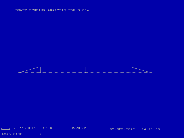
These are very close to the hand calculations. In both cases the maximum moment is greatest at the bearings, and when combined yield (406,1002 + 112,8002)1/2 = 421,474 N-cm.
CFRAME does not compute stresses, but at the point of maximum moment, assuming the 6.2 cm shaft diameter, the stress is (421,474 N-cm)/(23.4 cm3) = 18,011 N/cm2 = 180 kPa.
We now turn to the deflections, first the deflections for Case 1.

And then for Case 2.
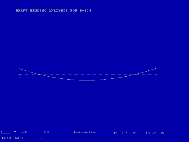
Deflection calculations are significantly more difficult than those of moment, and finite element software is very useful in this case. The maximum deflection in both cases is at the ends/eccentrics, and the combined deflection from CFRAME is (0.03642+0.0152)1/2 = 0.0384 cm, which is larger than those computed by hand. The deflections at the mid-point of the shaft are obviously of interest as well due to the shaft’s interaction with the rotor.
Another data item of interest is the angle of the shaft at the bearings, which from CFRAME is .003148 radians for Load Case 1 and .001407 radians for Load Case 2. This is obviously of interest in the selection of the bearings. This machine uses double row spherical roller bearings, which are more tolerant of shaft misalignment than, say, the cylindrical roller bearings common in American vibratory drivers. However, there may be other factors, such as the alignment of the bearing holes and mounts themselves, that drove this decision.
There are other things that could be done to make this analysis more complete, including but not limited to treating the shaft inertia as a distributed load and added the effects of variations in the shaft diameter, to say nothing of a better idea of the loads themselves and how they interact.
Detailed Output of CFRAME
1*-*-*-*-*-*-*-*-*-*-*-*-*-*-*
 PROGRAM CFRAME
 *-*-*-*-*-*-*-*-*-*-*-*-*-*-*


 RUN DATE = 07-SEP-2022
 RUN TIME = 14.21.09


 SHAFT BENDING ANALYSIS FOR S-834


 *** JOINT DATA ***

                          ------------------FIXITY-------------------
 JOINT     X        Y     X  Y  R      KX          KY          KR
           --- CM ---                  ---N   / CM---      CM-N  /RAD

    1    -28.20      .00
    2    -19.00      .00  *  *
    3       .00      .00
    4     19.00      .00     *
    5     28.20      .00


 *** MEMBER DATA ***

        END END
 MEMBER  A   B    LENGTH      I          A        AS         E          G
                    CM      CM**4      CM**2     CM**2      MPA        MPA

     1    1   2     9.20  .7253E+02  .3019E+02  .0000E+00  .2100E+06  .8077E+05
     2    2   3    19.00  .7253E+02  .3019E+02  .0000E+00  .2100E+06  .8077E+05
     3    3   4    19.00  .7253E+02  .3019E+02  .0000E+00  .2100E+06  .8077E+05
     4    4   5     9.20  .7253E+02  .3019E+02  .0000E+00  .2100E+06  .8077E+05


 *** LOAD CASE     1


 JOINT   FORCE X     FORCE Y     MOMENT
           N           N         CM-N

    1   .0000E+00   .4415E+05   .0000E+00
    2   .0000E+00   .4415E+04   .0000E+00
    3   .0000E+00   .3237E+05   .0000E+00
    4   .0000E+00   .4415E+04   .0000E+00
    5   .0000E+00   .4415E+05   .0000E+00


 *** LOAD CASE     2


 JOINT   FORCE X     FORCE Y     MOMENT
           N           N         CM-N

    1   .0000E+00   .1226E+05   .0000E+00
    5   .0000E+00   .1226E+05   .0000E+00


1              LOAD CASE     1


           JOINT DISPLACEMENTS
 JOINT       DX           DY           DR
             CM           CM           RAD

    1     .0000E+00    .3648E-01   -.4375E-02
    2     .0000E+00    .0000E+00   -.3148E-02
    3     .0000E+00   -.2383E-01    .0000E+00
    4     .0000E+00    .0000E+00    .3148E-02
    5     .0000E+00    .3648E-01    .4375E-02


                     MEMBER END FORCES
                                                    MOMENT
 MEMBER JOINT   AXIAL       SHEAR       MOMENT      EXTREMA    LOCATION
                 N           N          CM-N        CM-N          CM

    1      1   .0000E+00   .4414E+05   .0000E+00   .4061E+06     9.20
           2   .0000E+00  -.4414E+05   .4061E+06   .0000E+00      .00
    2      2   .0000E+00  -.1619E+05   .4061E+06   .4061E+06      .00
           3   .0000E+00   .1619E+05   .9859E+05   .9859E+05    19.00
    3      3   .0000E+00   .1619E+05   .9859E+05   .4061E+06    19.00
           4   .0000E+00  -.1619E+05   .4061E+06   .9859E+05      .00
    4      4   .0000E+00  -.4414E+05   .4061E+06   .4061E+06      .00
           5   .0000E+00   .4414E+05   .0000E+00   .0000E+00     9.20


           STRUCTURE REACTIONS
 JOINT     FORCE X      FORCE Y      MOMENT
             N            N          CM-N

    2     .0000E+00   -.6475E+05    .0000E+00
    4     .0000E+00   -.6475E+05    .0000E+00

 -------------------------------
 TOTAL    .0000E+00   -.1295E+06


1              LOAD CASE     2


           JOINT DISPLACEMENTS
 JOINT       DX           DY           DR
             CM           CM           RAD

    1     .0000E+00    .1504E-01   -.1748E-02
    2     .0000E+00    .0000E+00   -.1407E-02
    3     .0000E+00   -.1337E-01    .0000E+00
    4     .0000E+00    .0000E+00    .1407E-02
    5     .0000E+00    .1504E-01    .1748E-02


                     MEMBER END FORCES
                                                    MOMENT
 MEMBER JOINT   AXIAL       SHEAR       MOMENT      EXTREMA    LOCATION
                 N           N          CM-N        CM-N          CM

    1      1   .0000E+00   .1226E+05   .0000E+00   .1128E+06     9.20
           2   .0000E+00  -.1226E+05   .1128E+06   .0000E+00      .00
    2      2   .0000E+00   .0000E+00   .1128E+06   .1128E+06      .00
           3   .0000E+00   .0000E+00   .1128E+06   .1128E+06      .38
    3      3   .0000E+00   .0000E+00   .1128E+06   .1128E+06      .00
           4   .0000E+00   .0000E+00   .1128E+06   .1128E+06      .38
    4      4   .0000E+00  -.1226E+05   .1128E+06   .1128E+06      .00
           5   .0000E+00   .1226E+05   .0000E+00   .0000E+00     9.20


           STRUCTURE REACTIONS
 JOINT     FORCE X      FORCE Y      MOMENT
             N            N          CM-N

    2     .0000E+00   -.1226E+05    .0000E+00
    4     .0000E+00   -.1226E+05    .0000E+00

 -------------------------------
 TOTAL    .0000E+00   -.2452E+05


1                     MEMBER END FORCES
         LOAD                                               MOMENT
 MEMBER  CASE   JOINT   AXIAL       SHEAR       MOMENT      EXTREMA    LOCATION
                         N           N          CM-N        CM-N          CM


    1       1      1   .0000E+00   .4414E+05   .0000E+00   .4061E+06     9.20
                   2   .0000E+00  -.4414E+05   .4061E+06   .0000E+00      .00
            2      1   .0000E+00   .1226E+05   .0000E+00   .1128E+06     9.20
                   2   .0000E+00  -.1226E+05   .1128E+06   .0000E+00      .00

    2       1      2   .0000E+00  -.1619E+05   .4061E+06   .4061E+06      .00
                   3   .0000E+00   .1619E+05   .9859E+05   .9859E+05    19.00
            2      2   .0000E+00   .0000E+00   .1128E+06   .1128E+06      .00
                   3   .0000E+00   .0000E+00   .1128E+06   .1128E+06      .38

    3       1      3   .0000E+00   .1619E+05   .9859E+05   .4061E+06    19.00
                   4   .0000E+00  -.1619E+05   .4061E+06   .9859E+05      .00
            2      3   .0000E+00   .0000E+00   .1128E+06   .1128E+06      .00
                   4   .0000E+00   .0000E+00   .1128E+06   .1128E+06      .38

    4       1      4   .0000E+00  -.4414E+05   .4061E+06   .4061E+06      .00
                   5   .0000E+00   .4414E+05   .0000E+00   .0000E+00     9.20
            2      4   .0000E+00  -.1226E+05   .1128E+06   .1128E+06      .00
                   5   .0000E+00   .1226E+05   .0000E+00   .0000E+00     9.20


4 thoughts on “Checking the Soviets: Determining the Bending of the Shaft”