Welcome to vulcanhammer.info, the site about Vulcan Iron Works, which manufactured the durable air/steam line of pile driving equipment for more than a century. Many of its products are still in service today, providing reliable performance all over the world. There’s a lot here, use the search box below if you’re having trouble finding something. Also look at the end of an article, there are helpful links to more information with every post.
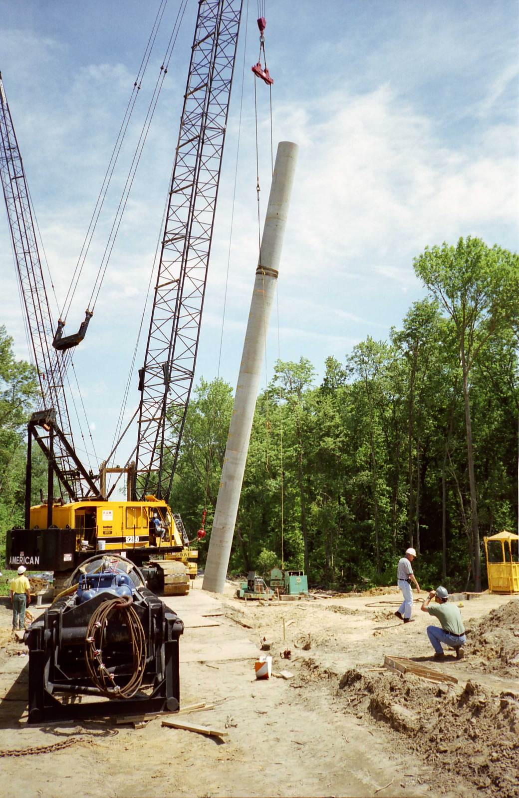
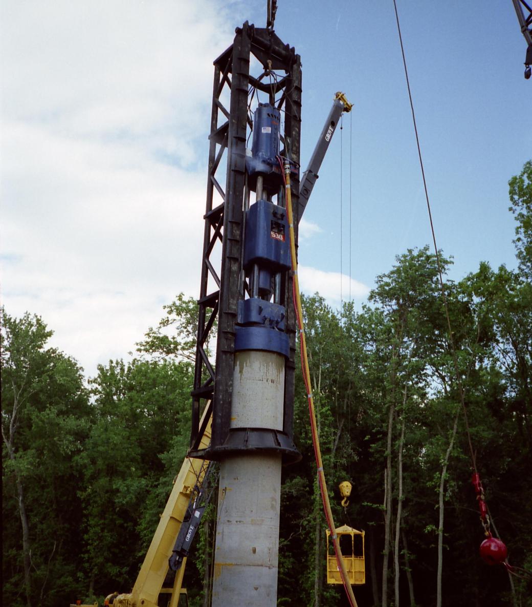
One of the concepts students in geotechnical engineering courses seem to have the most trouble with is estimating stresses in concrete piles during pick-up and setting them in place to drive. The basic problem is that it’s sometimes hard to get our heads around the analytical simplification of the actual situation. Let’s start by looking at the operation itself. These first photos come from a job in Delaware in 1998, using a Vulcan 530 to drive cylinder piles.
The pile starts on the ground. What we have here is “one-point pickup” where only one line is used to pick up the pile. It’s put in a certain place (more about that later) in this case using a “choker.” (Some piles have pickup lifting eyes, they are best cast into the pile at the time of manufacture.) In this position the pile is horizontal. Once the crane operator lifts the choker, the pile is supported at two points: the choker and the far end of the pile. This is the most severe case of loading during pick-up.The pile is being lifted into position. As the pile rotates, more of the load is shifted to the choker, but that load is more and more axial in the pile and not bending.The pile is now vertical, almost all the load is on the choker and the stresses in the pile are now axial.The pile is set into a template (shown in previous photograph) and the hammer is set on top of it, preparing to drive it. The template keeps the pile vertical until enough of the pile is in the ground to support it.The pile is nearly down to the desired elevation due to the blows of the impact hammer.
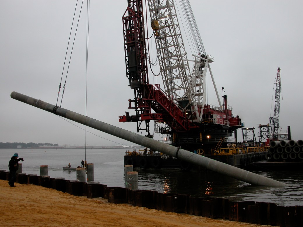
Depending upon the configuration of the pile, it’s also possible to have two- and three-point pickup, as we can see from these photos, taken at the construction of a terminal in Portsmouth, VA, in 2005-6. The contractor is Weeks Marine, the same contractor that got Sully’s plane out of the Hudson after his famous “landing” in the river.
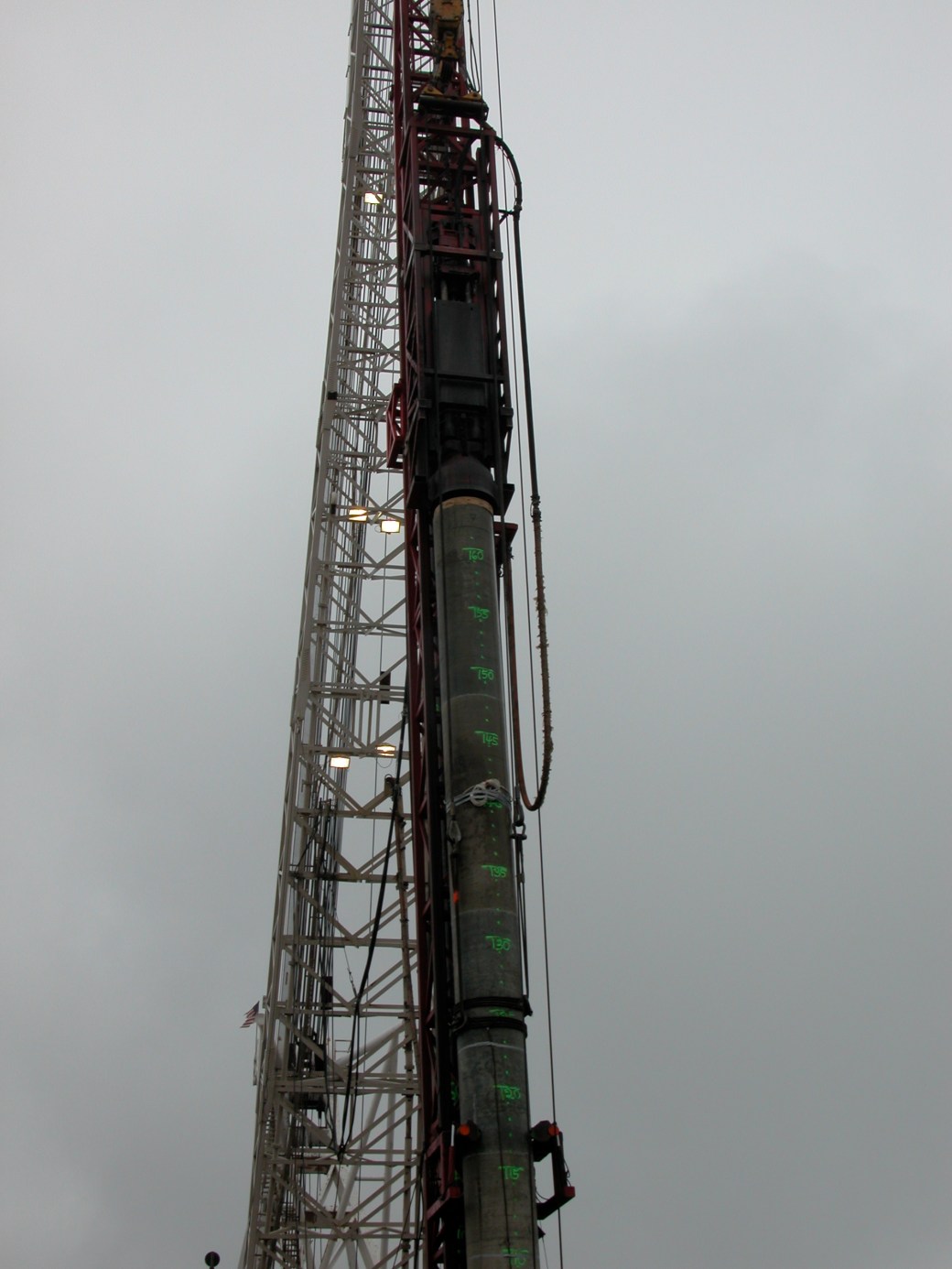
A two-point pickup of a cylinder pile. The pile is off the ground and horizontal; it is simply supported at the chokers. Behind the pile is Weeks Marine’s Raymond 60X hammer.The pile is being lifted up at one end for driving. As this happens more and more of the load is shifted to the left (top) choker, just as is the case with one-point pickup. Note Weeks Marine’s large barge which they use to do this kind of work.The pile is almost vertical, almost all of the load is on the upper choker, suspended in turn from Weeks Marine’s crane.The pile is now vertical. Weeks Marine’s Raymond 60X is now atop the pile, ready to begin driving. Note the grips on the pile at the bottom of the photo. This is called a “pile monkey” and is very useful for pile alignment in the leaders (guides.)
So how to we solve problems like this? Basically we assume that the pile is a horizontal beam, simply supported at the pickup points (or in the case of one-point pickup, at the pickup point and at the furthest end from the pick-up point) with the weight of the pile as the only load. One thing that can be done is to raise the distributed load of the weight by a factor for inertial effects during handling. An example of this is a 60′ long 12″ square concrete pile with a 50% increase for inertial effects with single point pick-up. We used the CFRAME program from the U.S. Army Corps of Engineers to analyse the beam, although most any beam software (or in some cases tables or hand calculation) can be used for this computation.
This slideshow requires JavaScript.
In this case we are displaying the output of CFRAME which shows each section of the beam/pile (i.e., one one side of the pick-up point and the other.)
According to the Prestressed Concrete Institute’s Recommended Practice for Design, Manufacture and Installation of Prestressed Concrete Piling (1993), the maximum permissible stress (tension) for transient loads such as handling loads is as follows
(US Units, psi for both variables)
For SI units, this works out to
(SI Units, MPa for both variables)
Some specifications allow the prestress of the pile to be added to , with the same units as the other variables. Obviously with precast concrete piles (rare in the US but used elsewhere) the prestress does not apply.
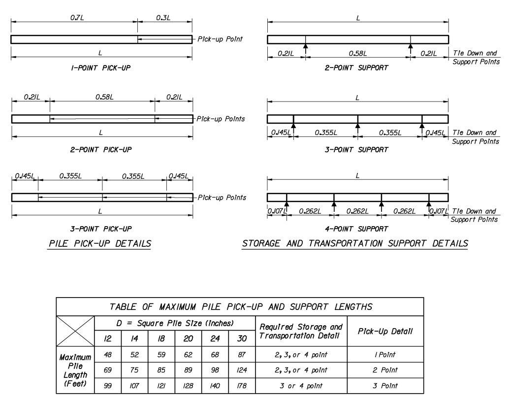
For several sizes of concrete piles, the Florida Department of Transportation recommends these permissible configurations and pick-up point locations. The pickup locations relative to the length are fairly standard with concrete piles.
Other piles sizes and lengths can be computed using the methods described above.


Reblogged this on vulcanhammer.net.
LikeLike