Above, an ad for the Warrington-Vulcan hammer, as featured in Engineering News-Record, 1926. Note that there are two distributors listed: one in California and the venerable Woodard Wight in New Orleans, which (with its salesman Herman Hasenkampf) went on to represent Vulcan in the Gulf during the offshore years. Note also that Vulcan even at … Continue reading Driving Speed That Makes Footage Records
Category: Uncategorized
Vulcan 0R Hammer: Specifications and Information
The Vulcan 0R hammer was the same as the #0 except that it had a heavier ram. It was relatively short-lived, its place was taken by the 010 hammer. Specifications for the hammer are shown below.
Vulcan #0 Hammer: Specifications and Information
First produced in 1912, the #0 hammer, although not the first Warrington-Vulcan hammer, is probably, in its own way, the most pervasive in its influence on the development of Vulcan's--and other--product line. The main Chicago general arrangement is above: others are below: Both the design, frame and accessory configuration of the #0 hammer were … Continue reading Vulcan #0 Hammer: Specifications and Information
Vulcan 06 Hammer: Specifications and Information
The 06 hammer is basically a #1 hammer with a 6,500 lb. ram. It uses the same leaders and driving accessories. An 06 at the Chattanooga facility is above, general arrangements of the hammer are below. Specifications for the Vulcan 06 are below. In the late 1970's Vulcan made an important … Continue reading Vulcan 06 Hammer: Specifications and Information
What We Need is a Light Trailer
In 1967 Vulcan opened a fabricating facility in West Palm Beach, Florida. Across the street from our new plant was “U and Me Transfer and Storage,” (see photo above) which we hired to move a lot of our machinery. We sent one of our supervisors to Florida to help set the shop up. The shop … Continue reading What We Need is a Light Trailer
Inverse Method for Pile Dynamics Using a Polytope Method: IFCEE 2018
New Version of TAMWAVE Online Wave Equation Program Now Available
The completely revised TAMWAVE program is now available. The goal of this project is to produce a free, online set of routines which analyse driven piles for axial and lateral load-deflection characteristics and drivability by the wave equation. The program is not intended for commercial use but for educational purposes, to introduce students to both the wave equation and methods for estimating load-deflection characteristics of piles in both axial and lateral loading.
We have a series of posts which detail the theory behind and workings of the program:
- TAMWAVE: Pile Toe Resistance, and Some More on Pile Shaft Resistance
- TAMWAVE 1: Entering Basic Soil and Pile Properties
- TAMWAVE 2: Modifying the Soil Properties
- TAMWAVE 3: Basic Results of Pile Capacity Analysis
- TAMWAVE 4: Shaft Resistance Profile, ALP and CLM2
- TAMWAVE 5: Wave Equation Analysis, Overview and Initial Entry
- TAMWAVE 6: Results of Wave Equation Analysis
- TAMWAVE 7: Analysis for a…
View original post 25 more words
TAMWAVE 7: Analysis for a Cohesive Soil
With the analysis of the concrete pile in cohesionless soils complete, we turn to an example in cohesive soils.
The analysis procedure is exactly the same. We will first discuss the differences between the two, then consider an example.
Differences with Piles in Cohesive Soils
- The unit weight is in put as a saturated unit weight, and the specific gravity of the soil particles is different (but not by much.)
- Once the simulated CPT data was abandoned, the “traditional” Tomlinson formula for the unit toe resistance, namely $latex q_t = N_c c $, where $latex N_c = 9 $, was chosen.
- The ultimate resistance along the shaft is done using the formula of Kolk and van der Velde (1996). This was used as a beta method, for compatibility with the method used for cohesionless soils. Unless the ratio of the cohesion to the effective stress is constant, the…
View original post 3,746 more words
TAMWAVE 6: Results of Wave Equation Analysis
With the data entered for the wave equation analysis, we can now see the results. There’s a lot of tabular data here but you need to read the notes between it to understand what the program is putting out. If you are not familiar at all with the wave equation for piles, you need to review this as well.
| Time Step, msec | 0.04024 |
| Pile Weight, lbs. | 15,000 |
| Pile Stiffness, lb/ft | 600,000 |
| Pile Impedance, lb-sec/ft | 57,937.5 |
| L/c, msec | 8.04688 |
| Pile Toe Element Number | 102 |
| Length of Pile Segments, ft. | 1 |
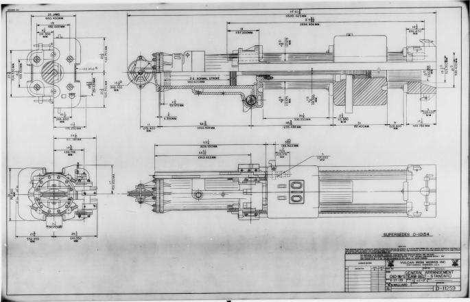
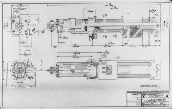
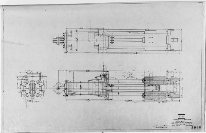
| Hammer Manufacturer and Size | VULCAN O16 |
| Hammer Rated Striking Energy, ft-lbs | 48750 |
| Hammer Efficiency, percent | 67 |
| Length of Hammer Cushion Stack, in. | 16.5 |
| Soil Resistance to Driving (SRD) for detailed results only, kips | 572.7 |
| Percent at Toe | 35.39 |
| Toe Quake, in. | 0.220 |
| Toe Damping, sec/ft | 0.07 |
For those familiar with the…
View original post 2,482 more words
TAMWAVE 5: Wave Equation Analysis, Overview and Initial Entry
With the static analysis complete, we turn to the wave equation analysis. TAMWAVE (as with the previous version) was based indirectly on the TTI wave equation program. Although the numerical method was not changed, many other aspects of the program were, and so we need to consider these.
Shaft and Toe Resistance
Most wave equation programs in commercial use still use the Smith model for shaft and toe resistance during impact. Referencing specifically their use in inverse methods, Randolph (2003) makes the following comment:
Dynamic pile tests are arguably the most cost-effective of all pile-testing methods, although they rely on relatively sophisticated numerical modelling for back-analysis. Theoretical advances in modelling the dynamic pile-soil interaction have been available since the mid-1980s, but have been slow to be implemented by commercial codes, most of which still use the empirical parameters of the Smith (1960) model. In order to allow an appropriate…
View original post 1,087 more words

