

The results of the Proctorsville project showed that our understanding of the mechanics of pile driving—and of the load transfer mechanism between pile and soil during and after installation—left a great deal to be desired. The solution to the problem was to instrument the pile driving process. Such an effort was documented in the 1908 paper entitled “The Supporting Power of Piles” by Ernest Goodrich, published in the Transactions of the American Society of Civil Engineers. It should be noted that, although the paper was published with comments in 1908, it was originally presented 5 February 1902. (An explanation of the term “power” is given in this monograph.) It definitely shows a form of instrumentation, but is it the first?
Recording of Blow Count and Set
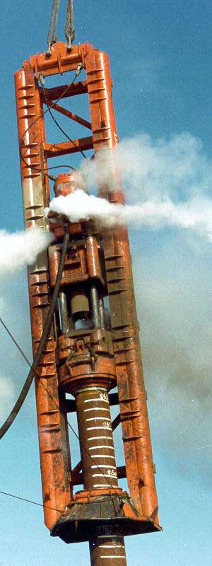
The dynamic formulae had one unarguable result: they established mathematically that there was some kind of relationship between the blow count/set of a pile and its soil resistance to driving (SRD.) This meant that it was imperative for the blow count to be recorded during installation. One simple way of doing this was to paint marks on a pile at definite distances between them and then count the number of blows it took to get from one mark to the next. This simple method even went offshore, long after the length of the piles obviated any residual validity that the dynamic formulae might have. This can be seen in the photo on the right.
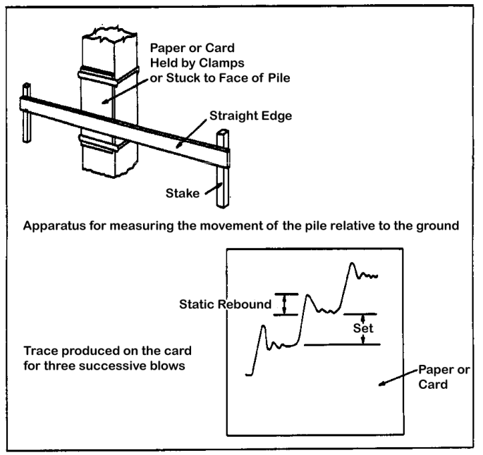
Another way was to mark a trace on paper which was affixed to a pile, as shown below (from FM 5-134, Pile Construction.) Simplifying this was the fact that it was done on concrete pile with a flat surface. Whether this can really be classified as “instrumentation” or was a practice in 1908 can be debated, but for the moment let us say that this isn’t quite instrumentation.
His Introduction and Theory
Goodrich begins with a brief history of driven piles. He then sets out the limitations of his study, which are as follows:
This discussion will be confined solely to the use of the common, tapering, round, wooden pile, driven by the ordinary gravity hammer, which is raised by a rope on a steam drum, falls by its own weight upon the head of the pile and thereby forces it to its destined place, where it is held simply by the contact of the surrounding soil.
We need to stop and consider what was going on in 1908, because advances in both hammers and piles were changing the landscape in a major way.
In the years since either the Proctorsville study or Wellington’s EN formula, steam hammers had come into their own. The Warrington-Vulcan hammers (at this point up to the #1 in energy) had been out there for almost two decades when Goodrich made his study; the #0 series would follow four years later. Vulcan had also introduced a sheeting hammer and of course it would not be long before the California series hammers would be introduced. Other manufacturers were also making steam hammers as well.
Goodrich implies that he is limiting his study to hammers which make direct impact on the pile. Vulcan was certainly capable of that. It’s not widely appreciated today but Vulcan’s classic cushion pot was designed around a conical receptacle on the base which was intended for trimmed wood piles to be inserted directly into the base. For those contractors which wanted a little more protection for the pile head, there were two options: the dished cap which was fitted to the hammer and the pile trimmed a little smaller, and the McDermid Base, which is still in use today.
In addition to the steam hammers, Vulcan was active in the drop hammer and drop hammer rig market as well. Direct impact wasn’t the only option for drop hammers; Vulcan manufactured its Casgrain cap (shown at the right) which included a hammer cushion. In noting Goodrich’s mention of steam hoisting, some of Vulcan’s drop hammer rigs were made for lifting the ram using literal horse power.
Probably more consequential to the industry at large was the introduction of piles other than wood piles. Concrete piles—especially associated with the Raymond organisation—were getting started, and their unique dynamics would ultimately upend the dynamic formulae more than just about anything else. Steel piles were appearing in both H-pile and pipe pile format. Steel sheeting was making its introduction in the Havana harbour.
Although it made sense for Goodrich to limit his study, technological changes were transforming the landscape for driven piles, and doing so rapidly.
The Interaction of Piles and Soils
Goodrich also describes an interesting experiment as follows:
An instructive experiment, throwing some light on the nature of the support given to a pile by the earth into which it is driven, is to take a box with a glass front, fill it with lightly compacted sand, and push down between the glass and the earth half-round sticks, similar to piles in shape. This experiment discloses the fact that a compact cone of earth is formed under the foot of a blunt stick, and remains there, being pushed forward through the ground as the stick descends. This cone acts exactly like the sharp end of a pointed stick or pile. It will always form under any load which soil is required to carry, and, consequently, the bearing power of the latter is one of the latter is one of the elements helping in the support of a loaded pile.
This kind of experiment confirms the conoid model that was set forth in the Proctorsville experiment (and which continued to be discussed later in the century.)
Analysis of the Dynamic Formulae
The pithiest analysis of this part of the paper was done by E. Sherman Gould, one of the original commenters:
This paper is valuable in that it exhaust completely the mathematical side of the question of pile-driving, which comes up at intervals with greater or less profit to the profession. No such thorough analysis as is given by the author can ever be deemed useless, because it either establishes a rational formula or demonstrates that none such can exist. It appears to the writer that this paper proves the latter proposition.
The dynamic formulae could not escape the limitations of simple Newtonian impact mechanics, especially since they did not consider the distributed mass and elasticity of the piles. That would have to wait another twenty years with the work of Isaacs.
The Instrumentation
The Proctorsville project and its analysis bracketed the Civil War, and the project where these piles were instrumented likewise related to that great conflict, then almost fifty years out: the monument to William Tecumseh Sherman, the Union general whose most famous campaign was his “March to the Sea” from Atlanta to Savannah and the march northward through South Carolina to the Confederacy’s “second surrender” in North Carolina. The monument is located near the Treasury Department and is not so far from the White House. As was typically the case, it was supported by wood piles, and those piles were driven directly by drop hammers.
Although Goodrich’s description of his first apparatus is hard to follow, describe it he did, and the diagram is shown in Figure 1.
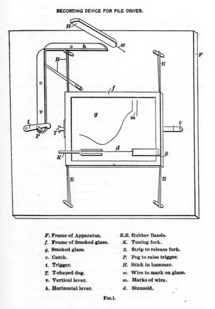
The purpose of this to produce displacement-time traces, and these are depicted in Figures 2-10.

The traces have a decidedly primitive look to them. Some show evidence of rebound (Figures 4 and 5) but others do not. In Figure 3 Goodrich attempts some basic differentiation to allow the displacement-time traces to be used to determine the velocity of the ram as it is brought to a stop.
There are a few takeaways from his work which are as follows:
- None of the stopping times—whether they be in the complete movement of the pile (where the hammer followed the pile until both stopped) or until the hammer had fully compressed the pile head—were as short as the 1 ms that Vulcan used to compute the force of the hammer on the pile head. Although these admittedly were restricted to a ram impacting a wood pile without a hammer cushion, some basic physics for both steel and concrete piles will show that this method of computing the force of the hammer results in unrealistically high values.
- He shows that the set of the pile is proportional to the square of the time it takes to stop the ram.
- Although the fall of the ram is reported, no where is the weight of the ram directly linked to a given test.
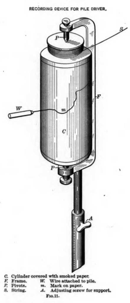
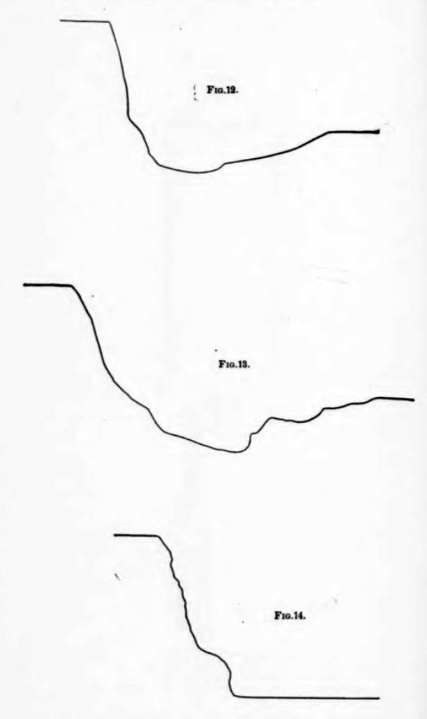
Goodrich switches his recording device to a drum type as shown in Figure 11.
This device is akin to—and may be a modification of—the indicator card recording devices that were common in steam engines in the day, something which Vulcan’s people would be well familiar with. The results are shown in Figures 12-14.
He attempts to differentiate the displacement curves to obtain a velocity, as shown in Figures 15 and 16.
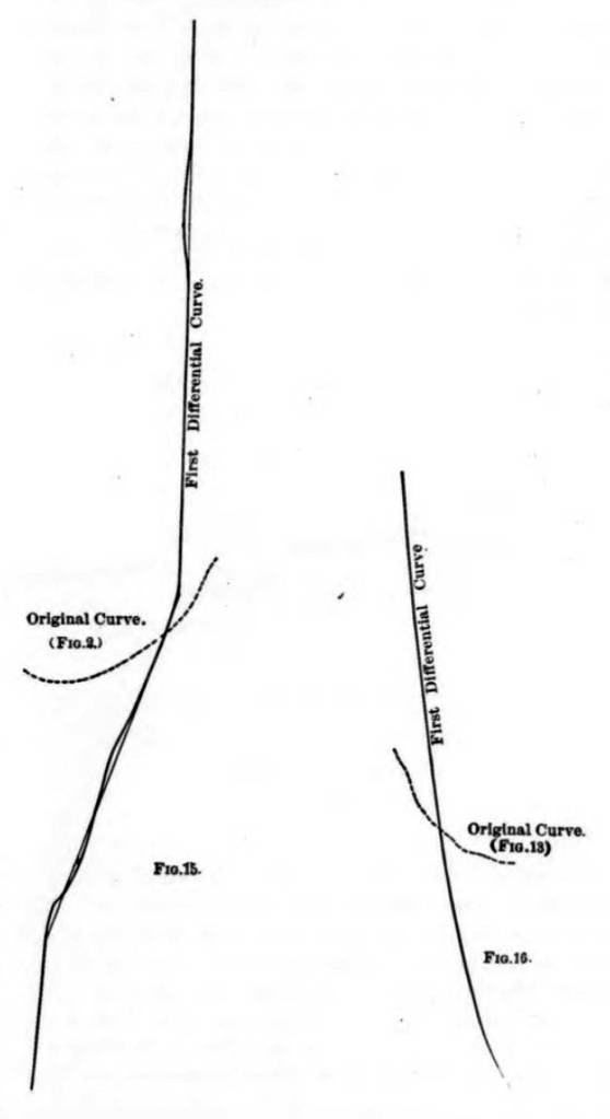
Goodrich draws one interesting conclusion to his experiments: “The curves also show that in the majority of cases the final intensity of the force was the same as the initial intensity.” Anyone familiar with pile dynamics knows that this is not the case, that the force rises and falls on the initial impact with the pile and that the “square wave” assumption is not realistic.
Measuring the Efficiency of the Fall
The apparent quality of Goodrich’s results improves—in part because the displacements are larger and thus easier to measure—when he takes on the issue of the energy losses during the fall of the ram. Goodrich pithily notes that “Few authors seem to think that the actual velocity with which the hammer falls differs materially from its theoretical value.” His experiment—the first that I am aware of which measured the efficiency of an impact pile hammer—showed that this was erroneous.
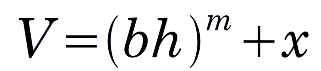
Goodrich is aware that the velocity of the ram at impact without any other resistance to its fall (including leader friction) is theoretically
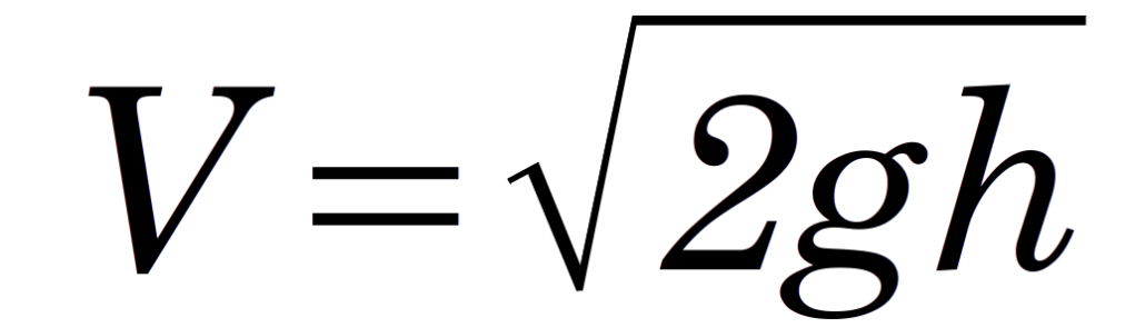
(1)
where V is the velocity at impact, g is the acceleration due to gravity and h is the fall of the ram. In our practice we would add an efficiency factor e to determine the net velocity of the ram at impact, thus
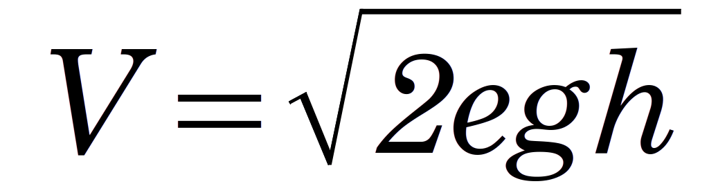
(2)
Goodrich, however, generalises the velocity with the following relationship
(3)
where b, m and x are constants to be determined by experiment. If we equation Equations (2) and (3) and solve for the efficiency, we have
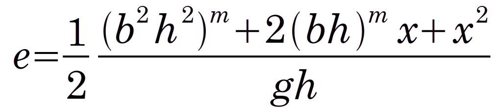
(4)
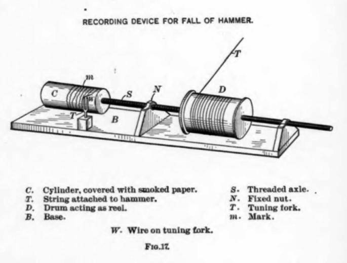
Goodrich used a device as shown in Figure 17.
The results he obtained are shown in Figure 18. It is evident that the ram takes longer to reach its “destined place” (to use Goodrich’s delightfully Calvinistic term) when there are resisting/frictional forces than when there are none.
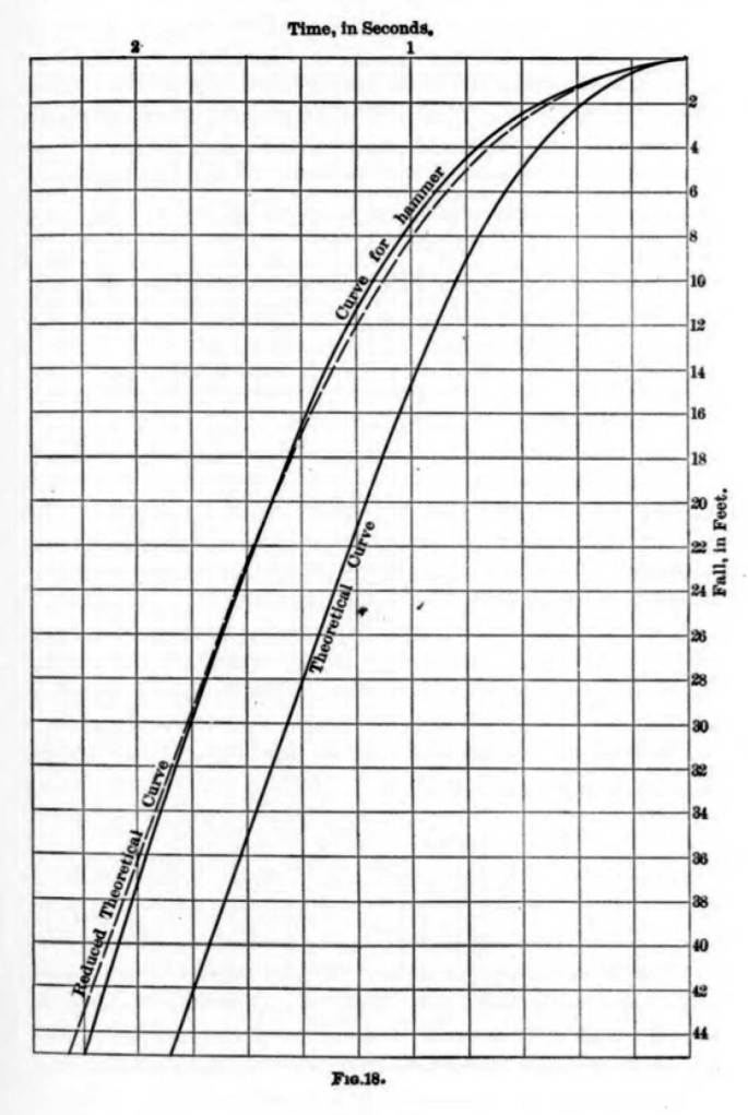
Goodrich used these curves to compute the values of the coefficients in Equation (3). Taking his result of b = 1.15g, m = ½ and x = 0, substituting these into Equation (4) yields a result of e = 0.575 or 57.5%, which is not an unreasonable value for a drop hammer rig. This efficiency—although not labelled properly—actually appears in one of Goodrich’s proposed formulae.
Although it’s likely that some of the formulae in use implicitly took hammer efficiency into consideration, making efficiency inclusion uniform in dynamic formulae would have at least made the factor of safety easier to sort out. The question of efficiency becomes even more complicated when air and steam hammers, with their varying constructions and states of maintenance and lubrication are introduced into the mix of pile driving equipment subject to the rating of a dynamic formula.
Energy Losses in Pile Driving
Probably the least satisfactory portion of Goodrich’s work was the part on energy losses in pile driving. The fundamental problem is that energy losses in pile driving were not well understood at the time, a topic further obscured by the nature of the dynamic formulae. Leaving out the topic of hammer efficiency, losses in pile driving include but are not limited to the following:
- Rebound of the hammer after impact, something which is not really addressed in Goodrich’s study. Rebound is not only the result of upward pile movement on the ram but due to the ram-pile interface itself, something that has been noted since Parola (1970) and Warrington (1987, 2020a, 2020b).
- Plastic deformation of the pile, and for those piles with hammer and pile cushions, the cushion. With directly impacted wood piles this was easily seen in brooming of the pile head.
- Losses due to pile and soil damping, which were not understood at the time and would have to wait until wave mechanics were employed.
Goodrich presents two diagrams during his narrative on the subject, Figures 19 and 20.
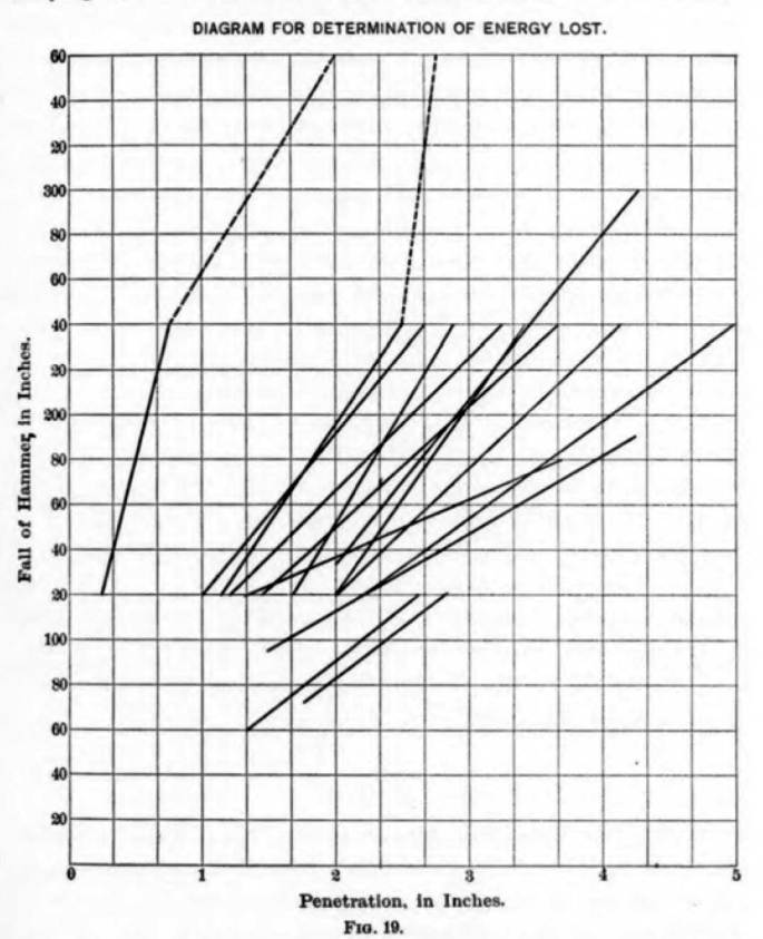
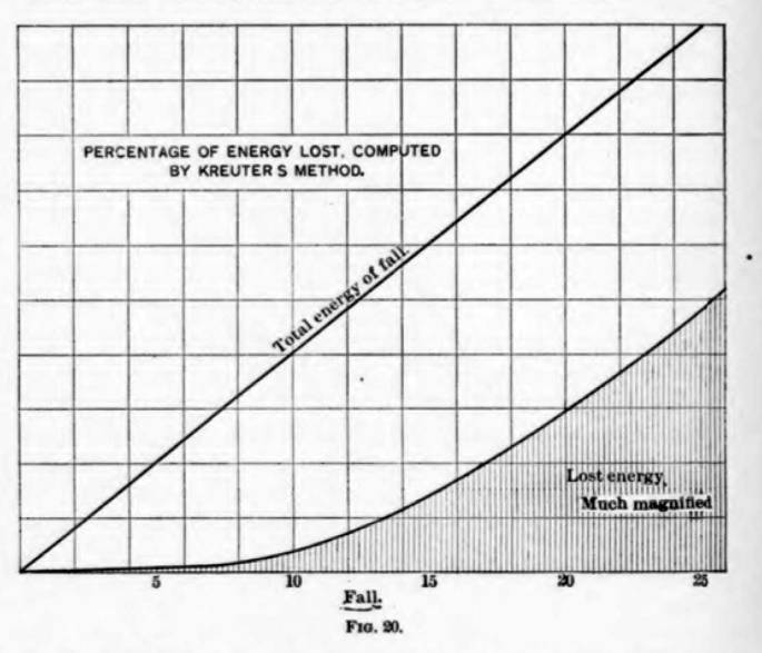
Figure 20 is interesting because it shows that, as the fall of the ram increases, the energy loss as a portion of the “total energy of the fall” (which probably didn’t take frictional losses into account) increases. This might be helpful for “heavy ram/short stroke” supporters but, as is the case with anything else regarding the energy lost in pile driving in this paper, it needs to be read with caution.
Comparing Goodrich’s Formula
In the course of his analysis Goodrich derived yet another formula, which he compared with a series of projects which, in some cases, dated back half a century. He compares those to the load tests that were run and those results are shown in Table 1.
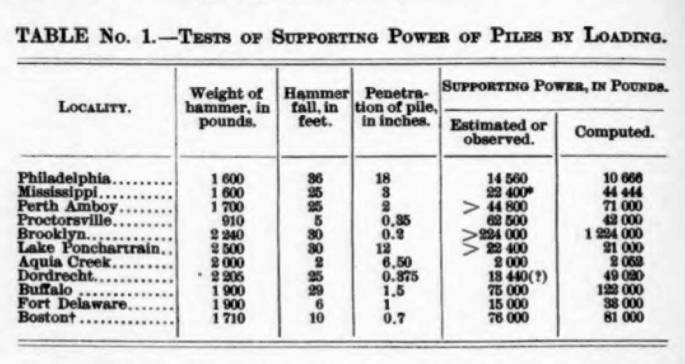
He makes some comparison with earlier formulae and especially Trautwine’s, and claims his is closer than that Trautwine’s in seven out of eleven cases. Going into this study, it is fair to say that Trautwine’s formula was probably the best dynamic formula available; its displacement by the EN (Wellington’s) was not an advance for driven piles.
A more mathematically meaningful way of comparing Goodrich’s formula with the load tests is to use least squares linear regression to plot the observed (presumably by static load tests of one kind or another) as shown below.
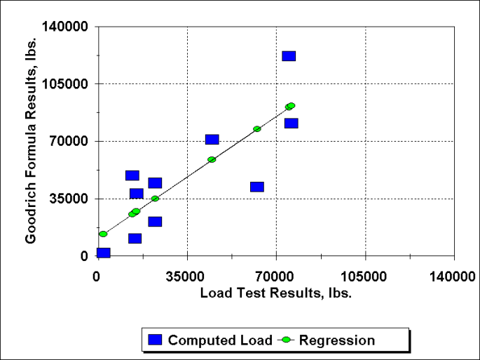
The equation of the linear trend line that results is y = 1.06 x + 11321, where x is the load test result and y is the Goodrich formula. We have thrown out the Brooklyn case as an outlier; that was where McAlpine’s formula was developed, with the difficulties of a formula without the set of the pile per blow. The equation basically shows that the Goodrich formula has an overall 1:1 increase in capacity relative to the tested capacity but with an 11 kip positive offset. The R2 = 0.66, which is not particularly good but then again geotechnical engineering is accepting of lower values of this parameter than other disciplines. It is also interesting to note that the data separates itself into two groups, one above the regression line and one below it; had Goodrich been able to pull the two groups together (especially pulling the upper group down to the lower group) his results would have been much more meaningful.
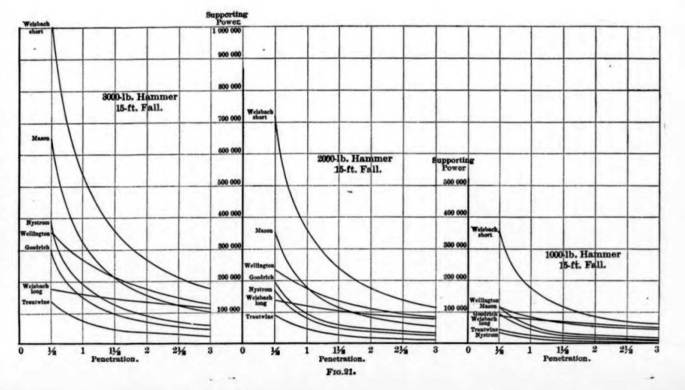
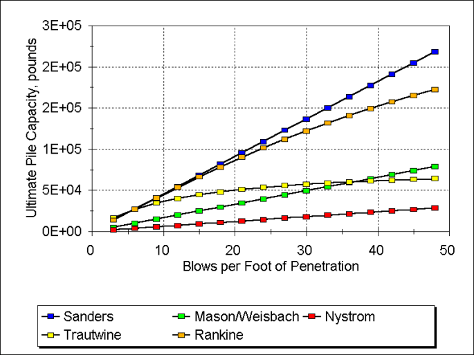
Figure 21 shows “bearing graph” results for a variety of formulae. It should be noted that the x-axis is set per blow and not blows per foot. (This kind of plot also appears in Isaacs.) It should be compared with the bearing graph developed for the Proctorsville project, which is shown below Figure 21. In both cases it is evident that the results of the dynamic formulae vary considerably from each other and that the EN (Wellington’s) formula has mainly succeeded in adding to the confusion.
Conclusion
Goodrich’s study, while thorough in its scope, is a decidedly mixed bag in its results.
His attempt to record the deflection-time history of the hammer impact on the pile outran the mechanical technology’s ability to keep up with the physics. Proper instrumentation of driven pile’s response to impact would have to wait until electrical/electronic technology could be applied to the problem, as took place with Glanville in the 1930’s (and later with Bror Fellenius in the 1940’s.)
His measurement of the efficiency of the fall was a major step forward. Had he presented the result in terms of that efficiency, he might have successfully encouraged derating some of the existing formulae, which in turn might have reduced the non-uniformities of the results reported by the formulae.
His biggest problem, however, was that he restricted his study to wood piles being driven directly by drop hammers. As noted, pile and hammer technology were on the move and the interaction between hammer and pile were becoming more diverse in nature and complicated in mathematical modelling. Concrete piles in particular upended Goodrich’s (and everyone else’s) paradigm, and solutions to the problems that resulted would lead to the studies of Isaacs and the application of the wave equation to piling.


4 thoughts on “Goodrich (1908): The First Instrumented Pile?”