
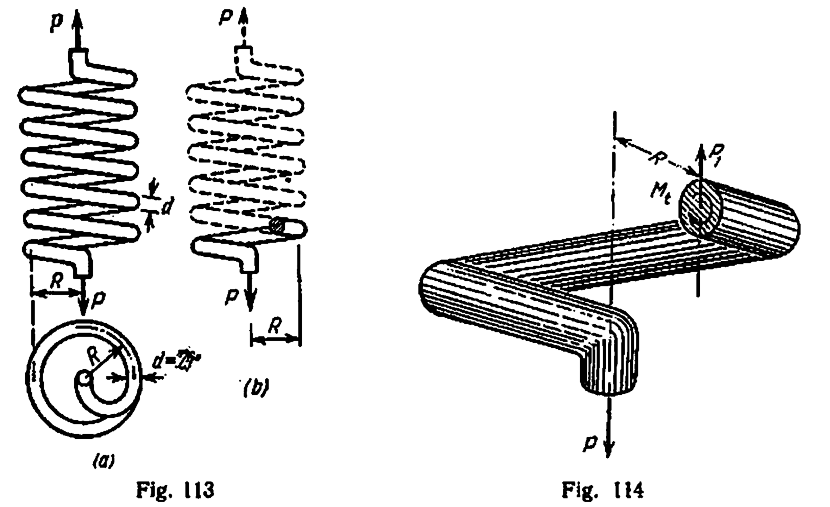
Coil springs never were a prominent part of most Vulcan hammers, but they did appear in spots and they are an important part of machine design. In this post we’ll go over the basics of these, based on Belyaev and Juvinall and Marshek (1985).

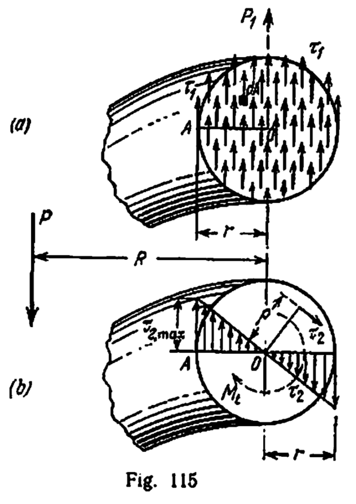
The tension or compression of springs puts the coiled wires into a combination of direct and torsional shear, as shown in Figure 115. There are two things we are looking for in coil spring analysis: the maximum shear stress in the spring, and the spring constant/load at a given deflection of the spring.
Let’s start with the spring constant, given by the equation

where
maximum shear stress on wire at a specific load
spring constant of spring
shear modulus of the spring material. For our examples below, the material is steel, and
pitch radius of the spring, i.e., the radius of the distance between the wire centrelines
radius of wire
number of active coils.
specific load on the spring
deflection of spring due to specific load

For a specific deflection,

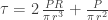
The shear stress is a little more complicated, because frequently formulations of this left out two important factors: the direct shear stress (see Figure 115(a)) and dynamic/stress concentration effects. With neither of these the shear stress is

With the direct shear stress included, the maximum shear stress becomes
Vulcan products without dynamic effects were the exception and not the rule, and the springs analysed below are no exception. To include dynamic effects the following formulation is used:

Juvinall and Marshek (1985) note that Equation (4) should be used for statically loaded springs and Equation (5) should be used for dynamically loaded springs. For our purposes we will use Equation (5).
Examples
We’ll present two examples of this, both from Vulcan’s diesel hammer efforts (or more accurately those of their partners) and both springs in their fuel pumps. The first is from Vulcan’s Belgian partner in the early 1970’s Nilens, and the spring is shown below.
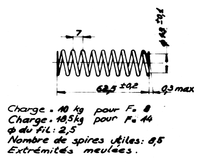
Based on the drawing above the dimensions for the equations are as follows: R = 7.75 mm, r = 1.25 mm, n = 8.5, G as shown above. Let’s check for the 18.5 kg load and see if it matches the 14 mm deflection shown above. If we do the substitutions we obtain the following:
- τ = 58.1 kgf/mm2
- k = 1.23 kgf/mm
- λ = P/k = 14.99 mm
The shear stress seems a little high, as we’ll see below. The deflection is close but not an exact match to the drawing.
The second one comes from Vulcan’s work with the Russians in the early 1990’s. This is a fuel pump spring from the V75 Series II hammer.

The wire size was given in the material specifications and was 6 mm. That being the case, the variables for our equations are as follows: R = 27 mm, r = 3 mm, n = 12.5, G as shown above. Let’s check the stress and deflection for the maximum load shown above, 65 kgf. The results are as follows:
- τ = 48 kgf/mm2
- k = 0.66 kgf/mm
- λ = P/k = 98.7 mm
The stress is within the material limit shown on the drawing of 56 kgf/mm2. The deflection is very close to the 100 mm deflection at this load shown on the drawing.
References
- Juvinall, R.C., and Marshek, K.M. (1985) Fundamentals of Machine Component Design. Second Edition. New York: John Wiley and Sons.


4 thoughts on “Analysis of Springs with Circular Cross Section”