
The Vulcan 560 hammer became the “#1 of Vulcan offshore hammers,” and the most popular of its offshore hammers from the 1970’s onward. Yet, although today the logic of a 5′ stroke hammer (especially when compared to the diesel hammers) is obvious, at the time it took a little persuading.
Vulcan had adhered to the “heavy stroke/low striking velocity” concept since the beginning, but by the early 1970’s the “race to the top” for hammer size–driven by the larger and deeper conventional platforms–was getting ahead of the barge capabilities of Vulcan’s largest customers. In the Gulf of Mexico that principally meant McDermott and Brown and Root, but also Santa Fe, Teledyne Movible Offshore and (a little later) Raymond. Basically when facing the need for a 300,000 ft-lb hammer, Vulcan’s “traditional” choice would be one like a 3100, which would weigh around 200,000 lbs. (100 US tons) plus cap and leaders. For many of the barges in the Gulf, that would necessitate the use of the main block to pick up the hammer and follow it as it drove the pile. The main block was okay for topsides and pile lifts, but in the constantly moving situation with a hammer, it was too slow.
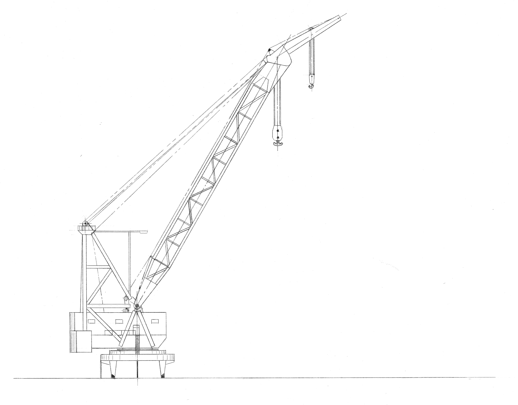
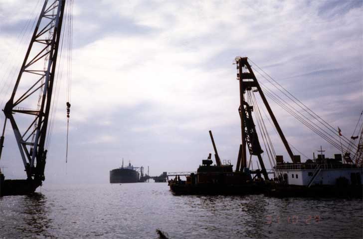
A typical offshore crane with the two blocks is shown below.
A lighter hammer would allow the contractor to drop to the secondary block on the crane, the traditional block to use for hammers. This block could raise and lower the hammer faster, and give the crane operator more control over the hammer during both lift and operation. (The mechanics of this are shown in the Appendix.) Vulcan “bit the bullet” and proposed the 560, which lowered the ram weight (and thus the frame weight) to around 30 US tons while preserving the striking energy with the 5′ stroke.
Vulcan presented the 560 to its customers, to mixed reviews. McDermott stuck with the 3′ stroke concept with the 3100. Its larger bench of barges–with the crane capacity to go with it–made the 3100 a more viable option for McDermott. But others–specifically Brown and Root–found the idea attractive, and B&R ordered the first 560 in early 1973. It was delivered later that year (a delivery which beat McDermott’s 3100 by almost two years!) and proved successful without too many “growing pains” such as were experienced with the 040 and 060.
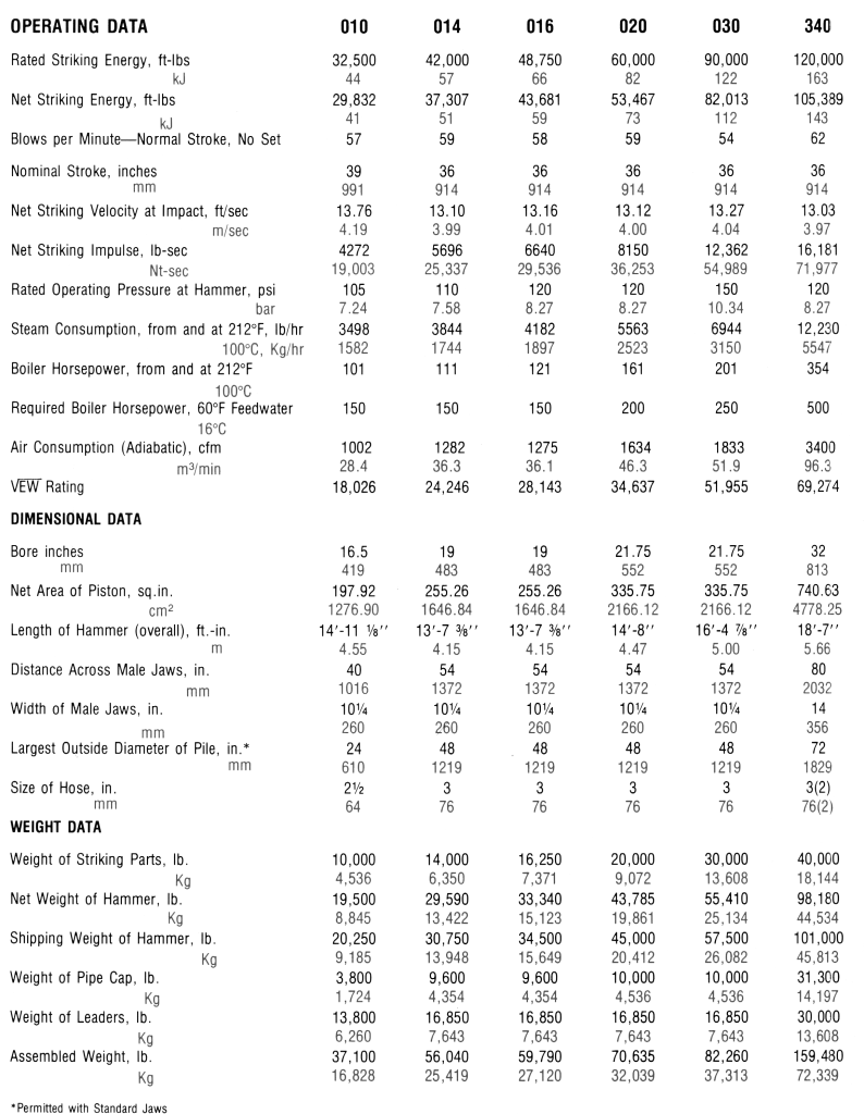
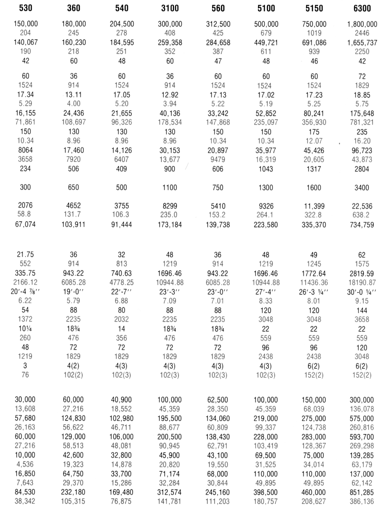
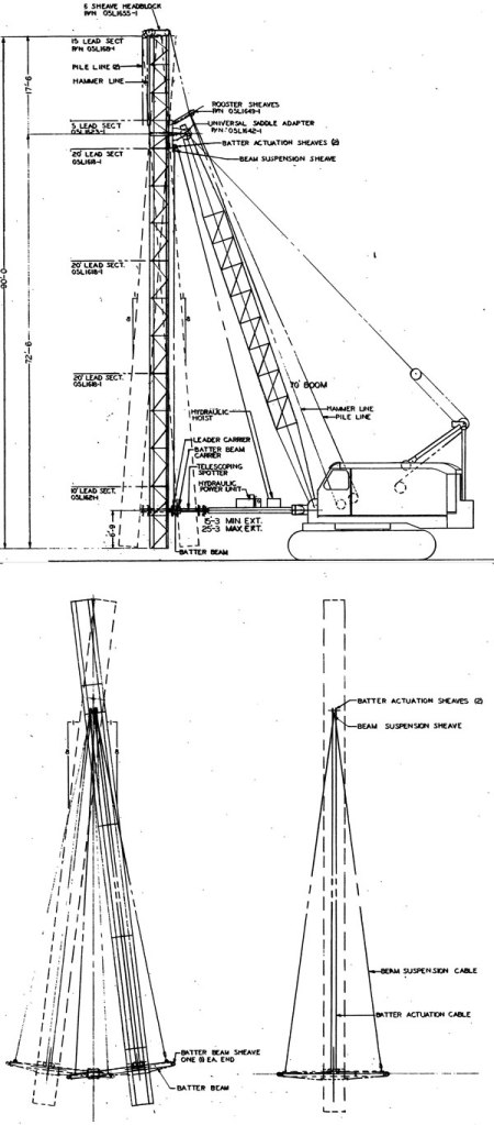
Specifications are shown below.
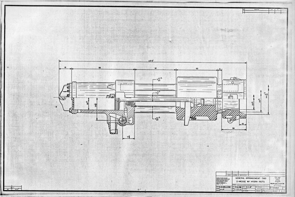
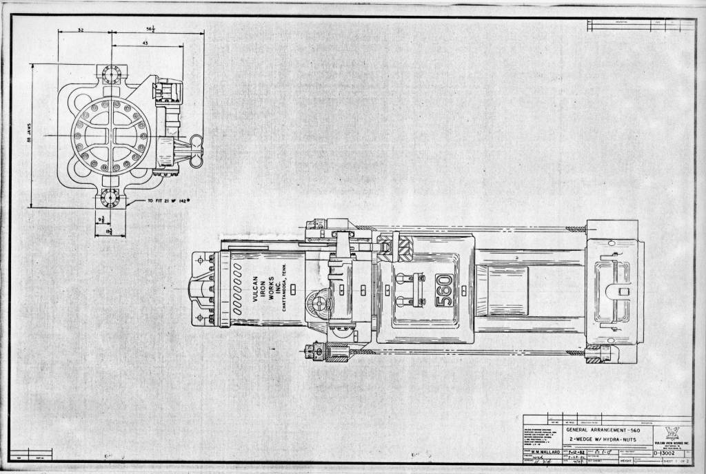
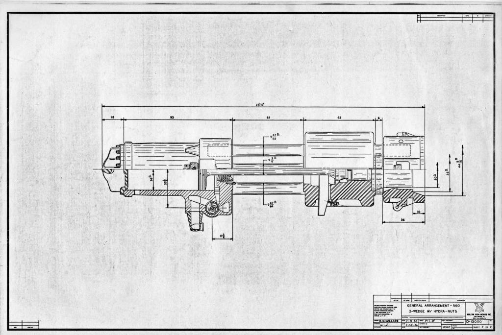
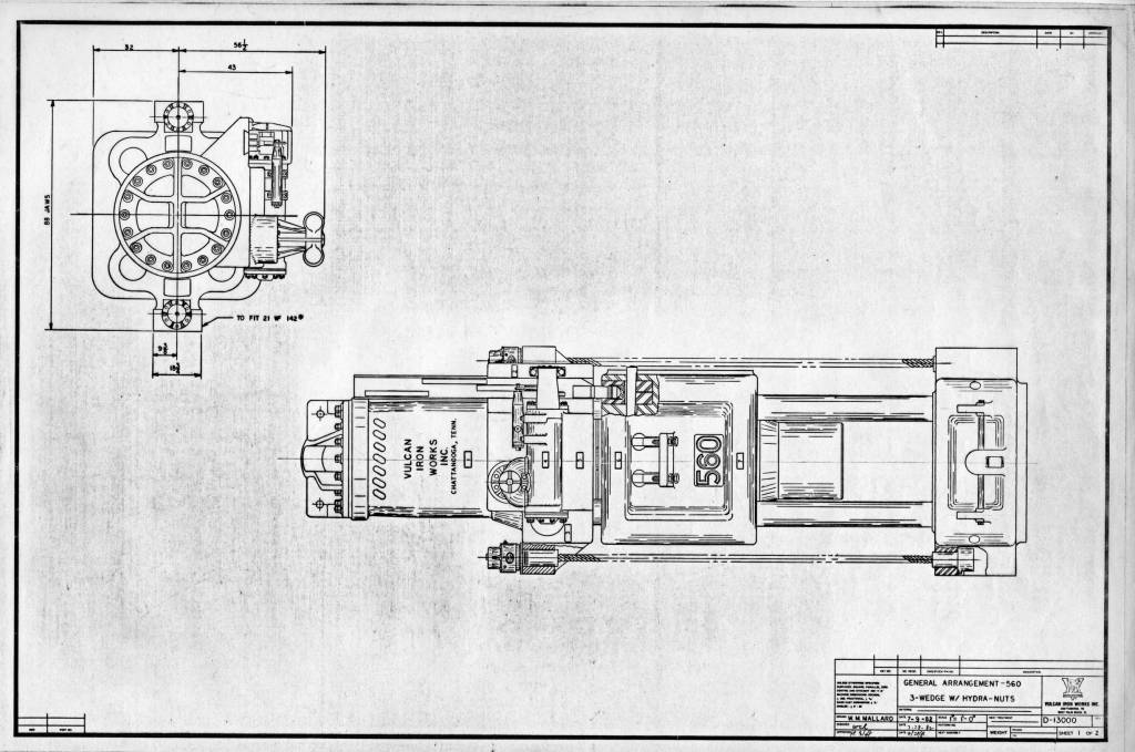
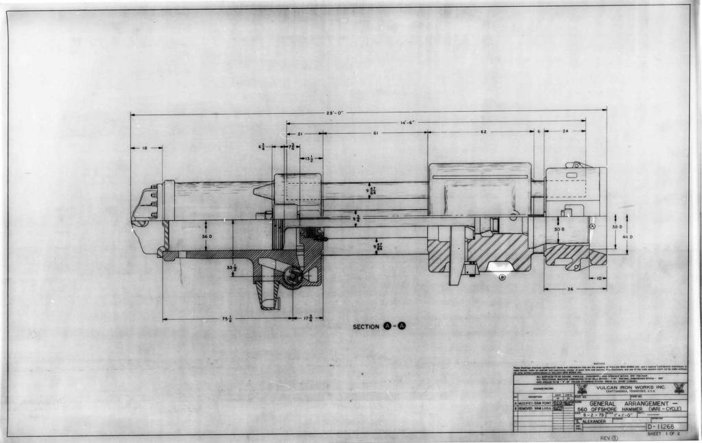
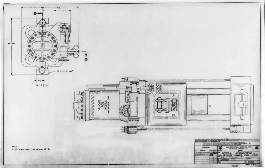
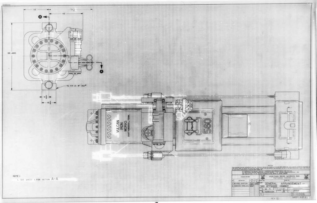
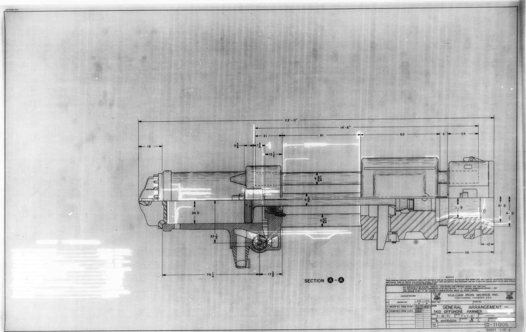
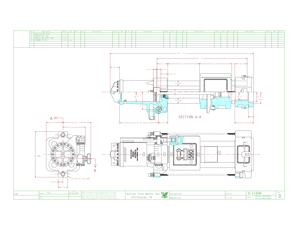
Some general arrangements–including later CAD ones from the 1990’s, showing the durability of the model–are shown below.
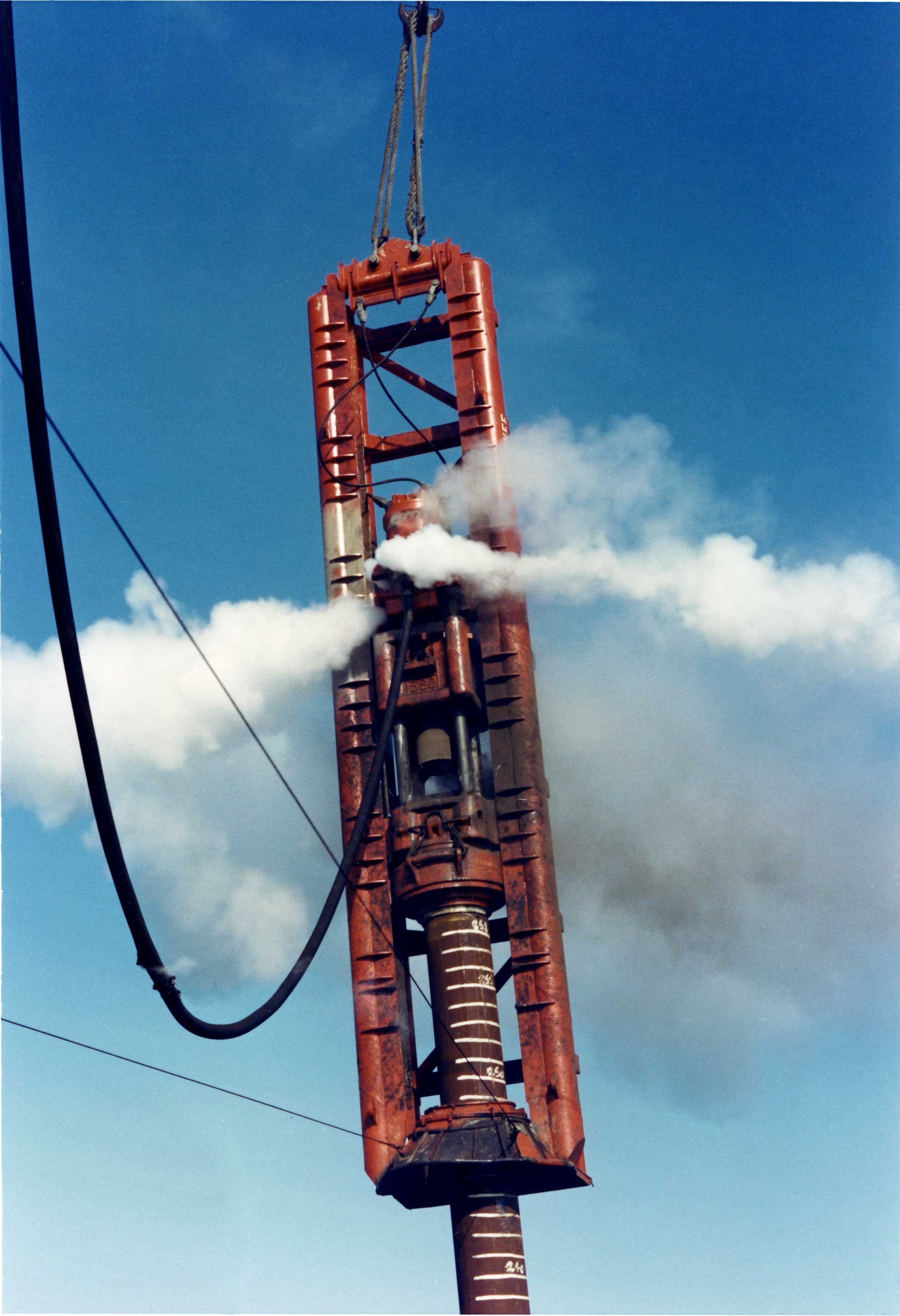
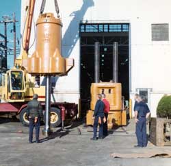
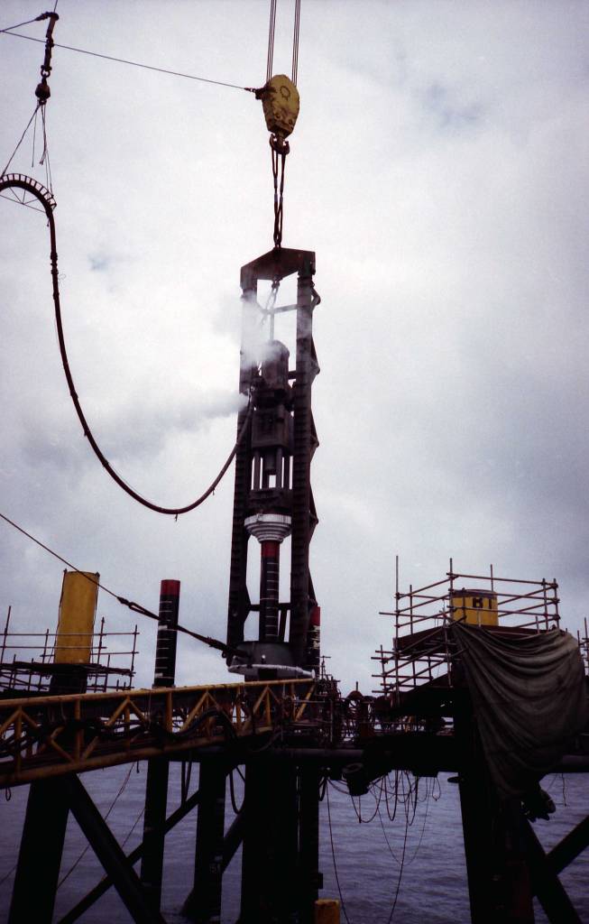
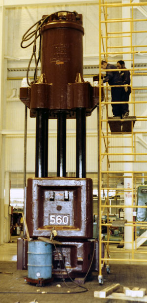
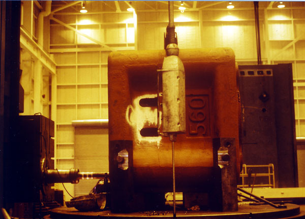
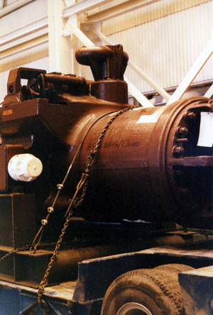
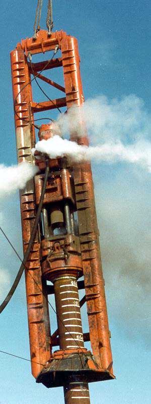
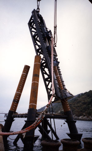
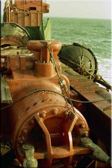
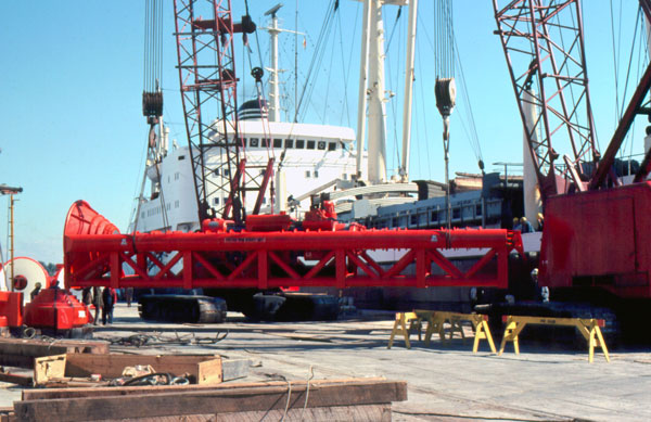
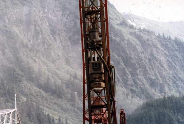
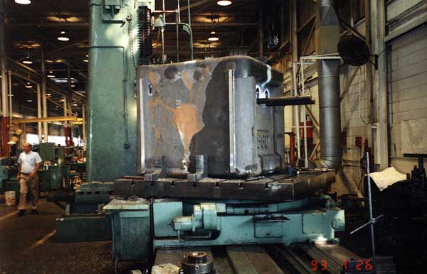
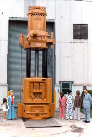
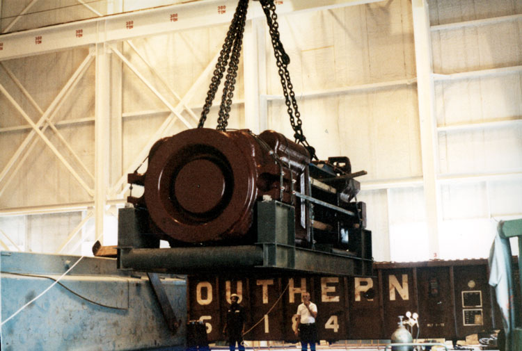
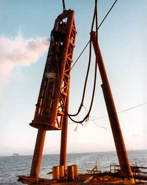
Some photographs of the hammer are shown here:

The 560 became the “standard” for offshore hammers, not only for Vulcan’s American customers but for its foreign ones as well, such as Micoperi, ENAP, Petrobras, Hyundai, Daelim, Jardine and of course CNOOC, the sale to which of two (2) 560’s is documented here. It also found onshore use with such customers as Manson Construction.
The irony of Vulcan’s “gamble” with the 5′ stroke is that it turned out to be an advantage. All other things equal (especially the cushion stiffness,) for a given energy a lighter ram with a higher impact velocity will produce an impact pulse with a higher peak force and shorter duration. With steel piles, this is something of an advantage; their ability to withstand the higher stresses allows higher impact forces and stresses. With concrete piles, a heavier ram and lower impact velocity is favoured, as it results in lower compressive and tensile stresses during driving. The stage was set for more 5′ stroke hammers, and the 560 not only was the first to try the concept but was its most popular example offshore.
Appendix: Mechanics of Sheave and Block Lifting Systems
The basic concept of sheave and block lifting systems has been around for a long time but some explanation of how it works and why it’s important is useful.
When most people think of picking up something with a crane, be it a pile hammer or anything else, they think of a single line that runs from the winch in the cab body up to the boom point (or beyond, using the example on the right.) The line turns around and connects to the load below it; the hammer (or pile, the two have separate lines in this rig) moves up or down according to which way the crane operator rotates the winch. Being a single line, if friction is neglected the line carries the entire load of the hammer or pile, and that tension load is transmitted in its entirety to the winch, which converts the load to a torque load for the winch motor.
For many years Vulcan hammers sported sheaves. These would divide the load but at a price, which is explained below. The availability of larger wire rope and winches have obviated the need for hammer sheaves on most Vulcan onshore air/steam hammers, and they are frequently picked up with a single line as shown in the drawing at the right. Diesel hammers have generally been lifted in this way from the start.
Offshore, the weight of the hammers made using a full-load line and winch impossible, thus a two block arrangement is as shown on the left and the hammer is hung off of the lower block. The explanation that follows comes in part from Smith’s Mechanic. This was the textbook that George Warrington used when he was at the University of Illinois; the edition linked to has a date of 1863.
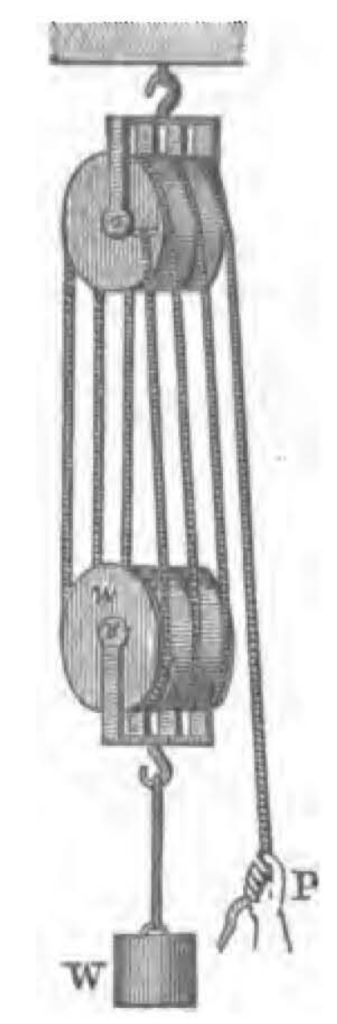
Consider the system to the left. We have two opposing blocks, each with the same number of sheaves and the same number of ropes running between the two. In this case we have six lines, starting at the side of the top block (the “dead end”) and looping through the sheaves until the end, which pulls up the load.
For a system where we have a load W and a lower block weight w, for n lines if we draw a free-body diagram which includes both weights, neglecting friction the load on each line P is
P = (W+w)/n (1)
Since it is a single cord, the load on each line is the same as the load P pulling the weight upward (or holding it in place.)
Thus, for a 560 package of 245,160 lbs., using a three sheave/six rope setup like this, and neglecting the weight w, the load to pull up the hammer is 245160/6 = 40,860 lbs. The mechanical advantage of this is clear, and the number of sheaves and ropes is not out of line with what one would see in practice.
There is a price to pay, however. First, the length of the wire rope which contacts the sheaves is, assuming we don’t (God forbid) jump the sheaves, constant. There are two lengths of wire rope which we need to consider:
- The length of the wire rope between the blocks, which we will call s1. As before there are six of these wire ropes.
- The length of the wire rope between the top block and the “hand,” which we will call s2.
The length of the wire rope at any time is given by the equation
l = 6s1 + s2 (2)
where l is the total length of wire rope (without the rope wrapped around the sheaves.) Since l is constant, we can differentiate Equation (2) to yield
0 = 6v1 + v2 (3)
where v1 is the velocity of the weight and lower block and v2 is the velocity of the “hand.”
Solving for v1,
v1 = -v2/6 (4)
We can thus see that the velocity of the load is only one sixth of the velocity of the rope which is connected to the winch. This can be generalised for a setup such as this as
v1=-v2/n (5)
The main block, being the block that does things like lift the platform in place, has a higher capacity–and achieves this by numerous sheaves and ropes using Equation (1)–than the secondary block, which has fewer of these ropes. Assuming the same winch speed for both, the advantage of using the secondary block for lighter loads–especially when the load lowers itself during operation, like a pile hammer–becomes evident.


10 thoughts on “Vulcan 560 Hammer: Specifications and Information”