
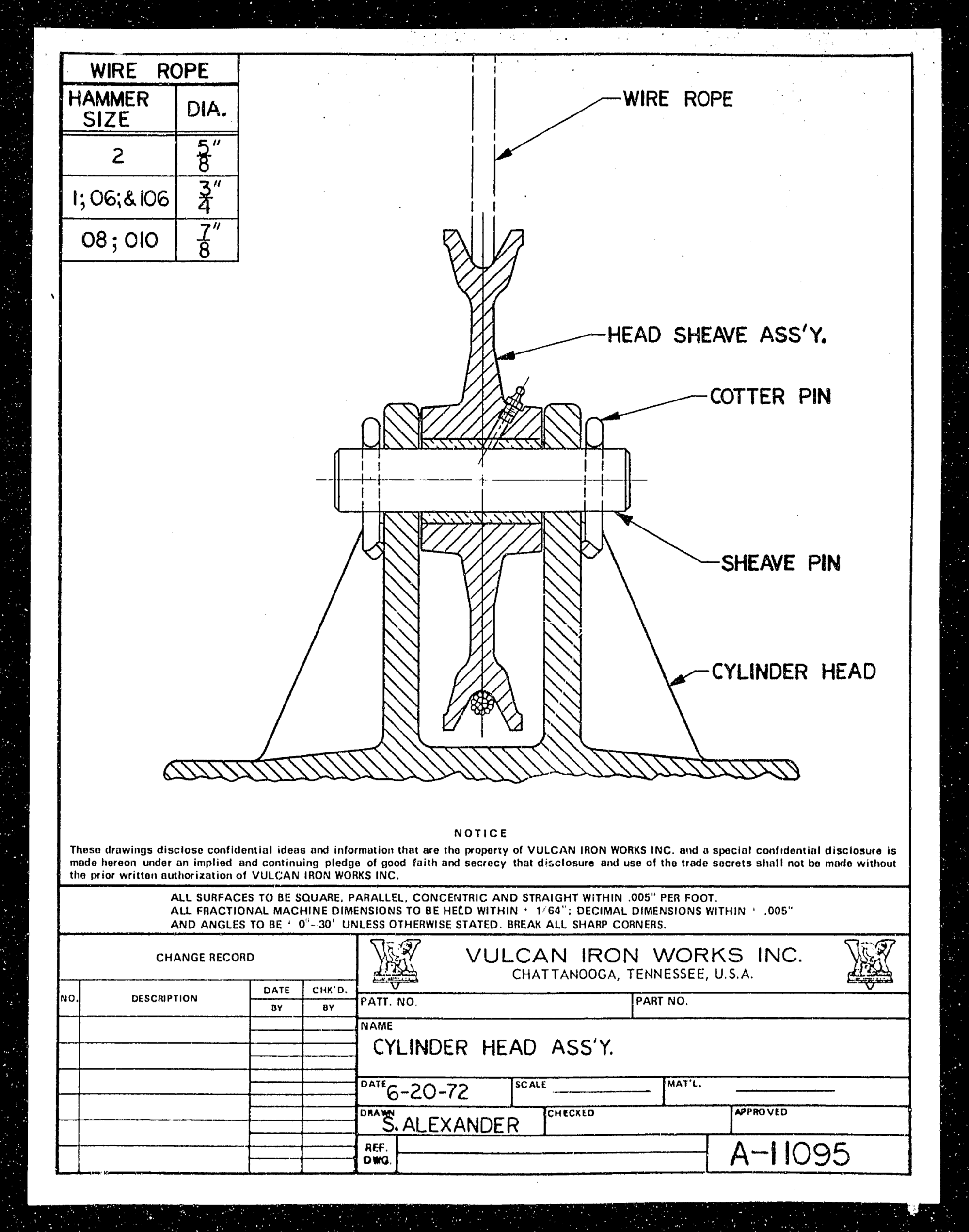
Above is a Vulcan diagram of the sheave and cylinder head assembly for Vulcan #2, #1 and #0 series hammers, which include the 06, 505, 506, 0R, 08, 010, 012, 508, 510 and 512 hammers. It includes the factory intended wire rope sizes for these hammers. Some additional notes are as follows:
- Sheave and sheave head assembly safety is VERY IMPORTANT; see Vulcan Tip #65 for more details.
- The grease fitting is there for a reason; the sheaves need to be greased periodically. See the Vulcan field service manuals for more information.
- Watch for wire rope and sheave wear, and replace when wear is excessive.
- Older Vulcan hammers will feature two sheaves where one is shown above; this can still be done if necessary if the hammer is in factory configuration with the proper sheaves.
- Vulcan traditionally assumed the “dead end” of the wire rope was on the leaders, while Raymond put it on the hammer, adding a dead end to the cylinder head to make this a reality.


One thought on “Vulcan Sheave and Cylinder Head Assembly”