
In the last post we looked at the SPW 2006 program analyze cantilever walls. In this post we will look at anchored walls, which are commonly seen with permanent works. The program, along with the example problem at hand, is here. Some instructions on the basic working of the program is here.
The problem we’ll be analyzing is once again from the BSC Piling Handbook (1984).
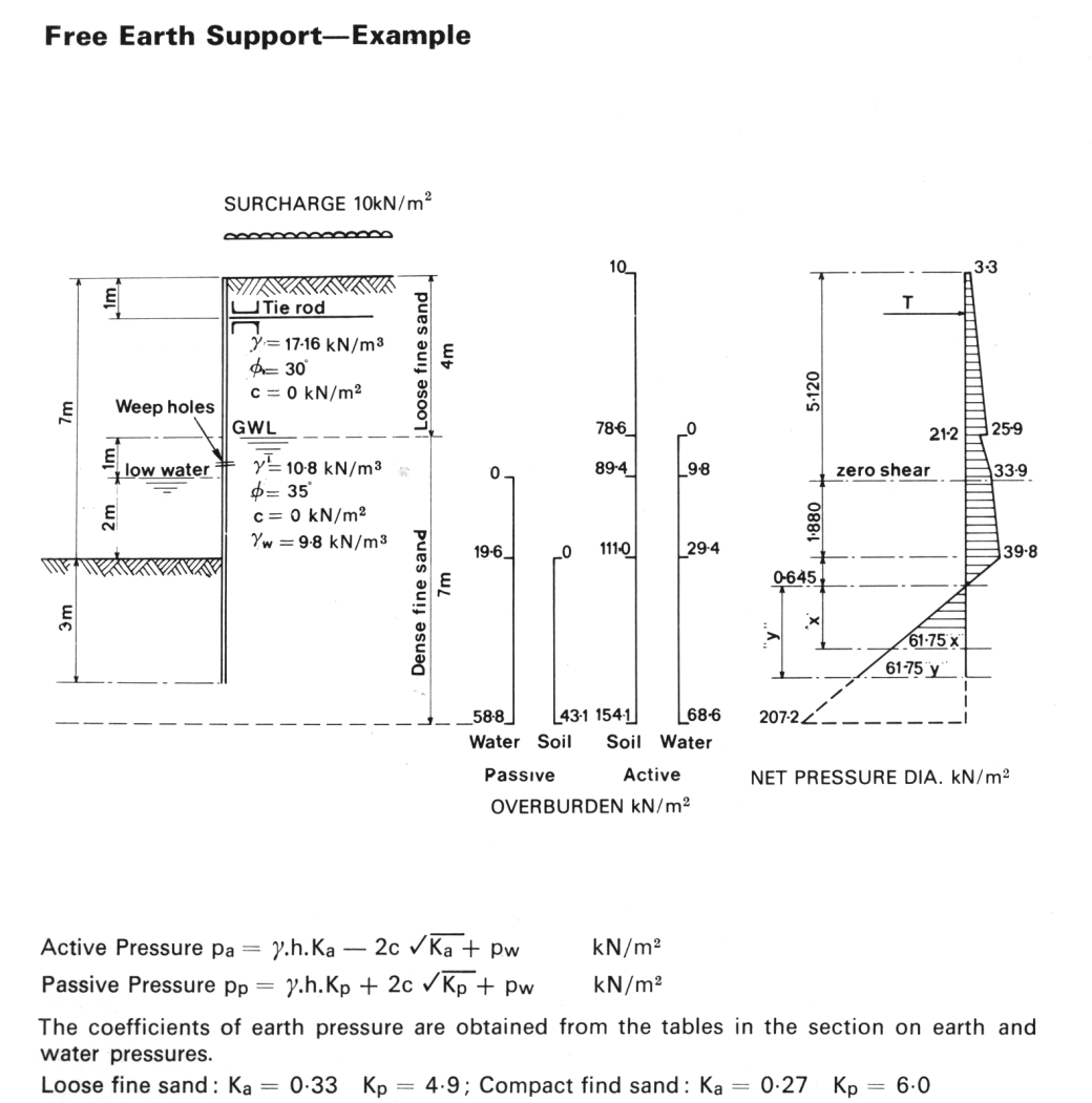
The soil profile input is similar to the cantilever wall except that it is necessary to put a layer boundary at the anchor point. Left and right side data, both tabular and graphic, are shown below.
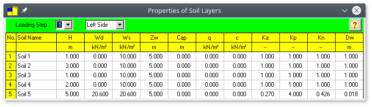
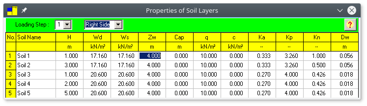
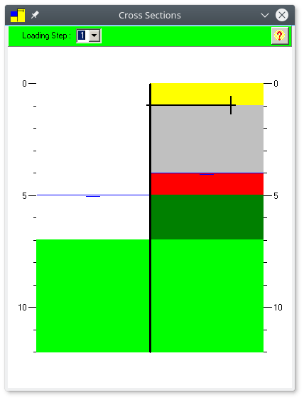
The same comments re Kp, Kn, q and Dw apply here as they do to the cantilever wall. Note that SPW 2006 allows the entry of differing water table levels on each side of the wall. Note also in the original BSC diagram that a weep hole is installed in the sheeting. Proper drainage is essential for the relief of unbalanced hydrostatic forces.
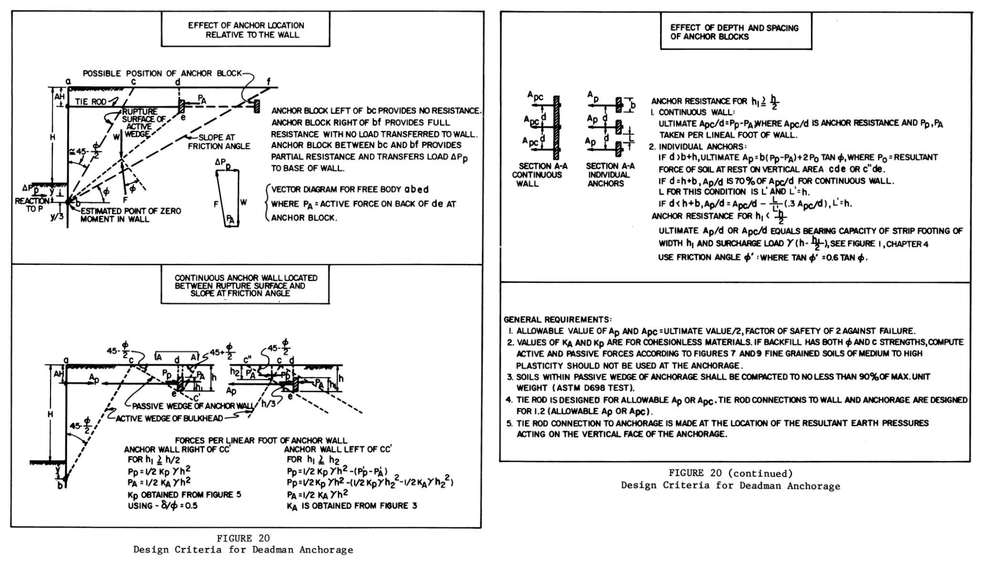
In any case the one input not present with the cantilever wall is the anchorage. SPW 2006 does not have provision for anchor design. A brief summary of this is given below, from DM 7; more information on this is found in Sheet Pile Design by Pile Buck.

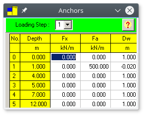
For our purposes we chose to specify a very stiff anchor, which renders the anchorage point essentially a fixed support, as shown at the right.
If one wants to consider the actual anchorage stiffness, it is necessary to determine the length, the cross-sectional area and the material to establish the stiffness, maximum stress and force, and the deflection at which plastic yielding takes place. If this is too much, a very stiff anchor is necessary; a very flexible anchor will render the calculations nearly useless. We have not included consideration of the flexibility of the soil bearing against the deadman; this further complicates the anchor input.
The graphical output (using PZ-22 sheeting) is shown below.
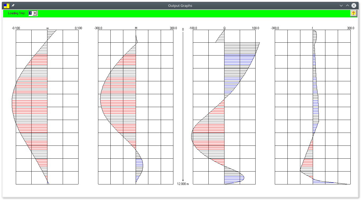
It is left as an exercise to show that the sheeting is adequate (or not) for the moment, using the same considerations as for cantilever walls.
Because of the soil-structure interaction, it is (in principle) unnecessary to apply Rowe’s moment reduction technique. That technique was developed to address deficiencies in the classical methods, which did not consider the interaction of the flexible sheeting with the relatively soft soil. Also, the technique of increasing the sheeting depth until a workable model is achieved is essentially a “free-earth” method. It is possible to apply the end conditions of the fixed earth (Blum’s or elastic line method) method; however, it can be tedious. Obviously SPW 2006 is happy to analyze sheeting lengths longer than the minimum required for geotechnical stability, and so if one wants to reduce the maximum moment (and thus the sheeting profile) a solution between the two can be found.
General Comments
As an educational tool, SPW 2006 fits the bill nicely. It requires very few system resources and no installation. It has a very comprehensive and detailed input and uses soil-structure interaction methods which are becoming more common with retaining wall software. (OTOH, many engineers and owners are not “sold” on SSI, and prefer “classical” methods.)
For use in design, SPW 2006 simply lacks many of the convenience features that one expects with commercial software, and these can make using the program a time-consuming and mistake-prone business in a commercial environment. For those who want to graduate from strictly classical methods to SSI ones, it can be very useful for both training and as a check. But commercial use of this program is not recommended.


4 thoughts on “Analyzing Sheet Pile Walls with SPW 2006: Part III, Anchored Walls and Some General Comments”