
In our last post, we introduced the SPW 2006 sheet piling software, intended for educational purposes. The software can be downloaded here. In this installment we’ll look at its application to cantilever walls, i.e., those walls with no additional support other than the soil itself. These are used in temporary works. The file for this can be found with the software.
The problem is this one, taken from the BSC Piling Handbook, Fourth Edition (1984).
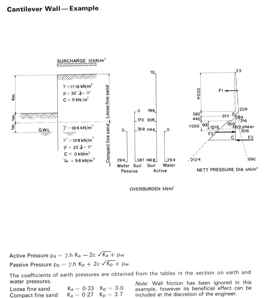
This is a fairly simple problem except that it has two different soil layers and properties. We’ll use the active and passive earth pressure coefficient values given in the example, although these can easily be computed from equations given in Verruijt or DM 7.
Based on this, the left side soil profile after input looks like this:
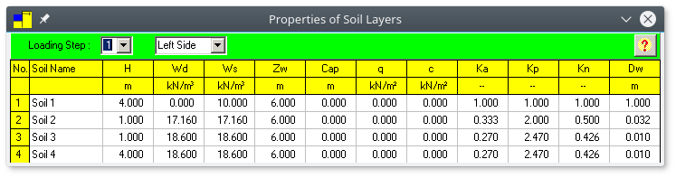
And the right side:

We note the following:
- The difference between the two is the first layer on the left side, as we would expect.
- We have a uniform surcharge
which is carried from the top downwards. It’s possible to vary that surcharge with depth; however, the program has no method of automatically computing variations in surcharge loading due to surface loads such as line and strip loads. Also, note that the surcharge is only on the right side. You have to manually check to make sure this is so; it is rare that there will be a surcharge on the left side.
- The water table level is shown in all layers.
- The passive earth pressure coefficients have been reduced by a factor of 1.5. There is more than one way to include a factor of safety for earth pressure; these methods are discussed in Sheet Pile Design by Pile Buck.
- The Kn (“neutral” or “at-rest” earth pressure coefficient) has been computed using Jaky’s Equation, discussed here.
- The stroke is probably the “stickiest wicket” in terms of soil properties. There are several ways of computing this, depending upon the amount of information on the soil you have at hand. Probably the simplest way to do this is to use a chart such as appears in DM 7, which is reproduced below.
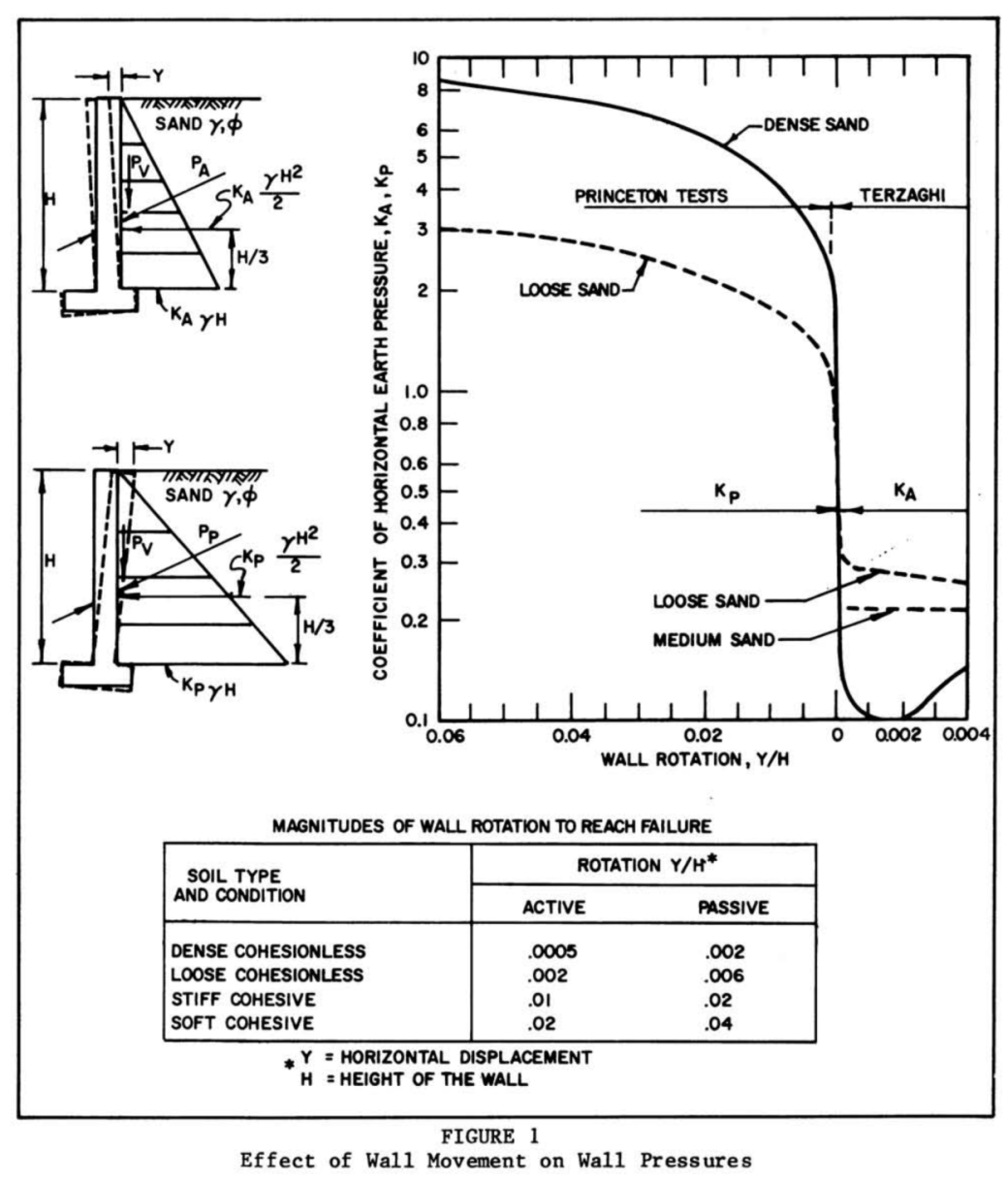
Selecting the proper case from the table at the bottom, the stroke can be computed as follows:

It is possible to be very precise with this calculation. For example, one could estimate the penetration below the dredge line 

In any case the soil profile looks like this:
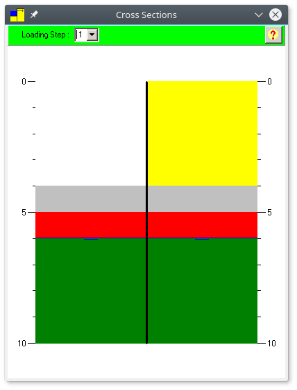
The correspondence of the sections with the original problem is easily seen.
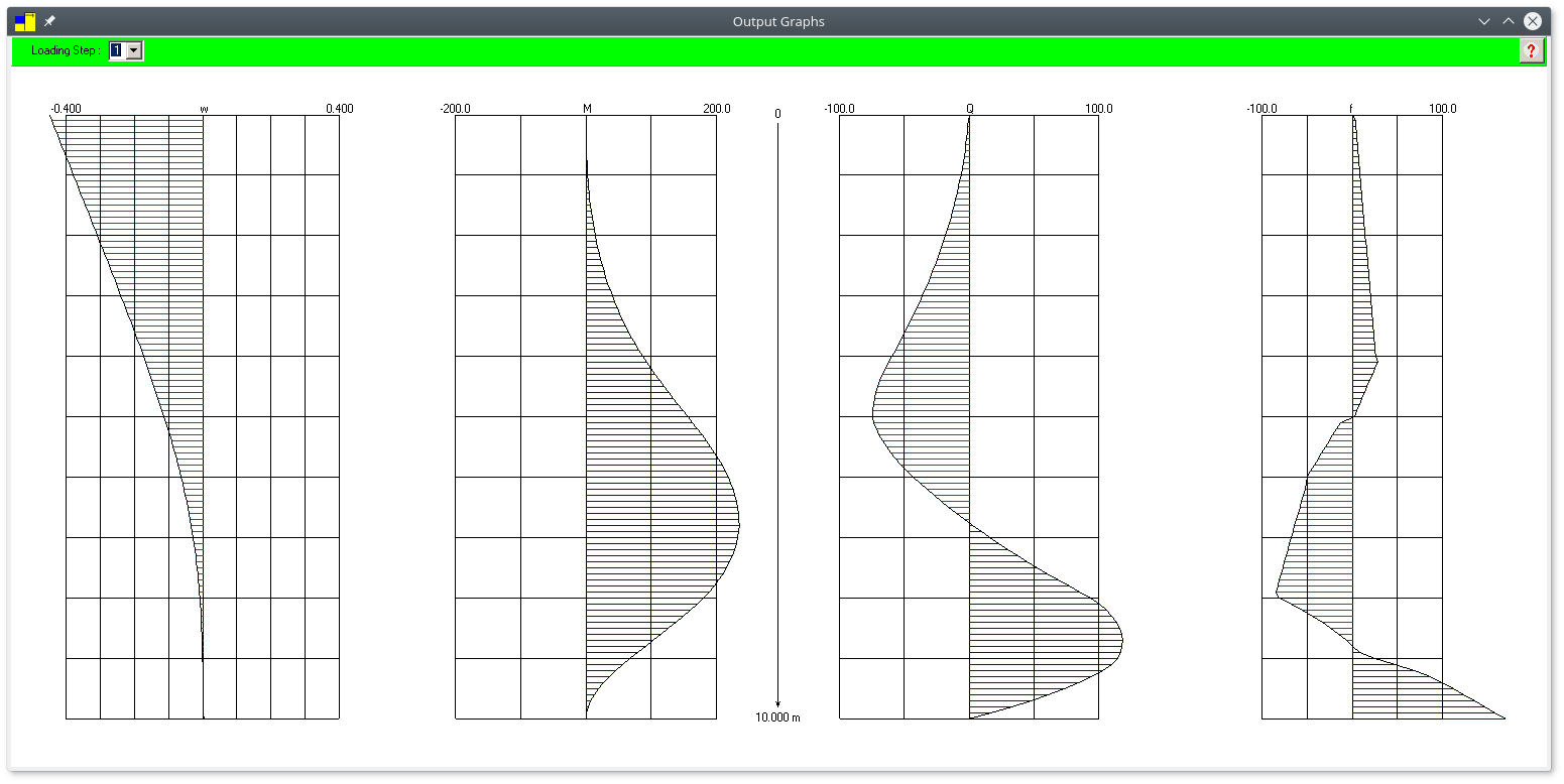
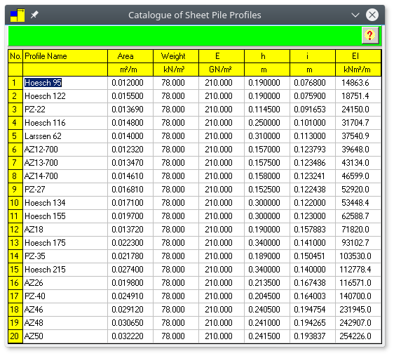
Now we select a sheeting length and a profile. We’ll select a length of 10 m (you will need to iterate from a short length, perhaps 6m and go upwards until you get a result that does not produce an error.) We’ll also start by assuming Profile #1 (Hoesch 95.) Running this yields the following beam diagrams:

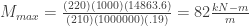
The maximum moment is around 235 kN-m/m. But is this section suitable for this level of moment? The simplest way is to compute the maximum moment the sheeting section is capable of, and this can be done using the equation
![M_{max} = \frac{\sigma_{max}\left[EI \right]}{Eh}](https://s0.wp.com/latex.php?latex=M_%7Bmax%7D+%3D+%5Cfrac%7B%5Csigma_%7Bmax%7D%5Cleft%5BEI+%5Cright%5D%7D%7BEh%7D+&bg=ffffff&fg=333333&s=0&c=20201002)
Here 


Assuming that the sheeting is made of ASTM A572 Fr. 50 with an allowable stress of 220 MPa, for Hoesch 95 the maximum moment is as follows:
Obviously this is too light of a section for the moment level. This indicates that the EI of an acceptable section should be 
The solution printout is here.
In the next post, we will consider the case of an anchored wall.


4 thoughts on “Analyzing Sheet Pile Walls with SPW 2006: Part II, Cantilever Walls”