
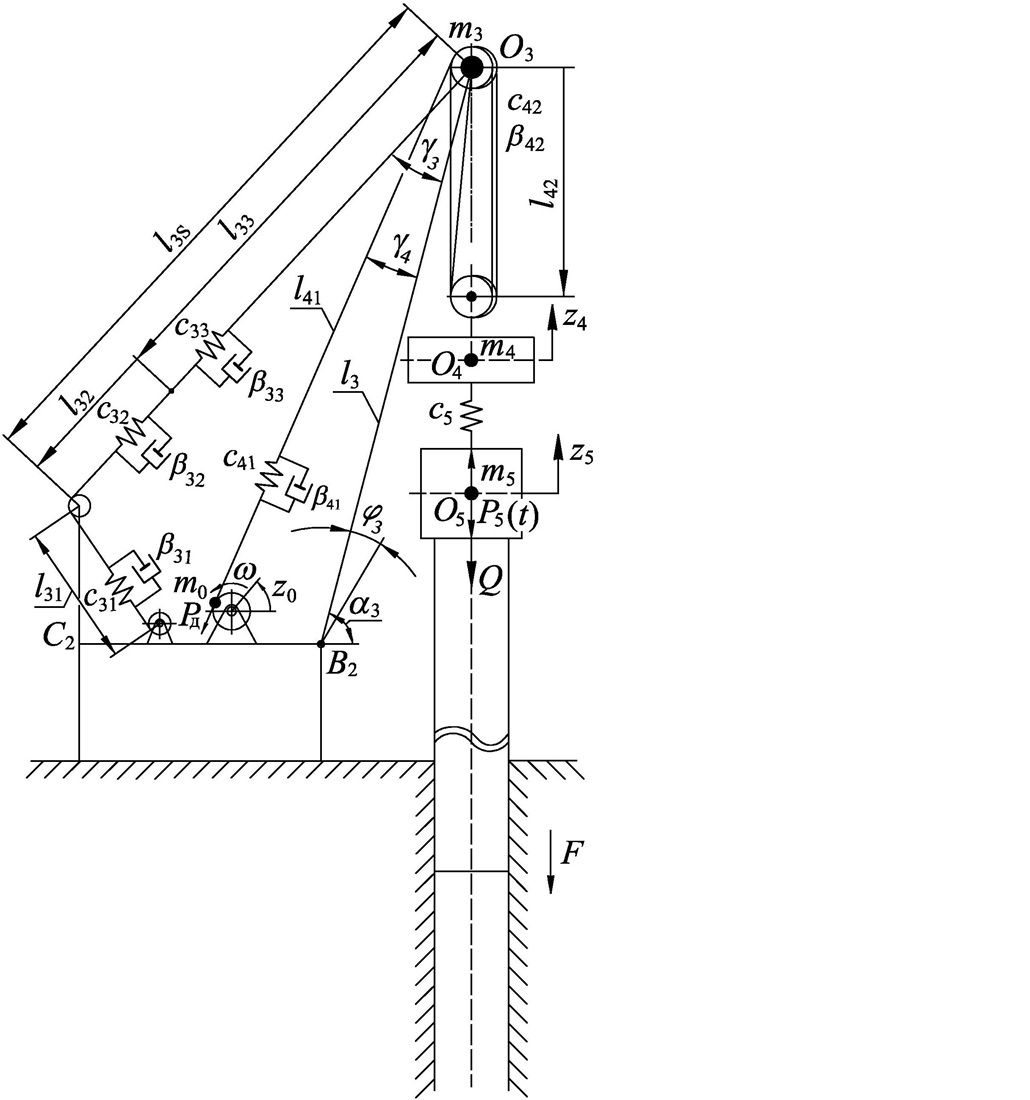
It is my custom to link to and make comments on papers which cite my work. This paper is titled Construction of a mathematical model of dynamic loads in a jib self-propelled crane when pulling a sheet pile out of the ground. It comes from Ukraine, and it is the first study of its kind that I’m aware of in that it models the entire crane/vibrator/soil system for the purpose of estimating the vibratory loads that are transmitted to the crane. It models the entire system, as shown in the figure above from the paper. It does so using Lagrange equations and is run for several cases of a specific vibrator and crane configuration. The work of mine he cites is Analysis of Vibratory Pile Drivers using Longitudinal and Rotational Oscillations with a Purely Plastic Soil Model, which is an interesting choice since no suspension is involved in the paper.
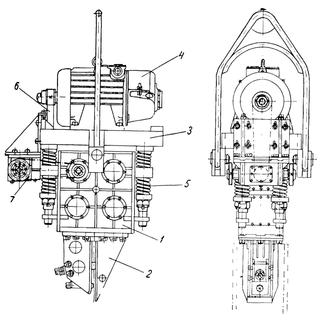
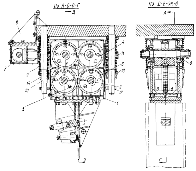
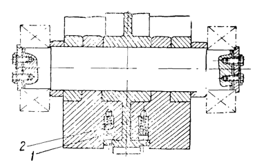
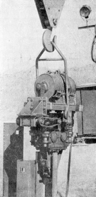
The vibrator they used is the VPP-2 (above,) which goes back to the beginning of the technology and is featured extensively in The Vibration Method of Driving Piles and Its Use in Construction. (Figures from this chapter.)
The study is fairly involved from a mathematical standpoint; my Dynamics students would find it a challenge. Without going into an extensive “blow by blow” of the method itself, I have a few comments:
- Although it was okay for the first round, I am not convinced that, for detailed studies, the crane boom should be modelled as a rigid body. There are doubtless beam type vibrations taking place in the boom, some of which could be significant.
- The VPP-2, as you can see, used coil springs for the suspension. Most vibrators manufactured today both here in the US and elsewhere use rubber springs. This would involve adding a damping component in this part of the model; additionally, the danger of “closing the gaps” with increasing tension from the crane, although exceeding the design load of the springs–which could result in tearing failure–must be considered. As a “full disclosure,” I didn’t include damping in my paper Development of a Parameter Selection Method for Vibratory Pile Driver Design with Hammer Suspension.
- I’m not sure I would have used a dry frictional model for the soil, especially since it is an extraction study. I’m not sure whether the authors used a purely Coulombic model or used a “ramped to Coulombic” model such as was described in Immersion and Extraction by Longitudinal Oscillations, but from my first use of a Coulombic model in Reconstructing a Soviet-Era Plastic Model to Predict Vibratory Pile Driving Performance I found them to be “fussy” for lack of a better term. A damped model such as I had frequent recourse to starting with Survey of Methods for Computing the Power Transmission of Vibratory Hammers would have been more stable and (possibly) easier to include in a parametric study.
- I found them referring to the eccentrics as “unbalance shafts” and “unbalances.” I made this correction frequently when posting the books I have the last several years.
- The model included a multi-line hoisting system. Many American vibratory hammers are lifted with a single line, which would simplify the modelling of the system.
Overall, this study is an excellent step in the right direction concerning the interaction between vibratory pile drivers and the cranes that lift them, and I hope to see follow-up in the future.

