

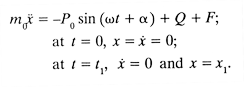
As we treat the process of sinking and extraction by means of longitudinal vibrations, we shall restrict the stable periodic movement of the vibrating system to a period equal to one revolution of the eccentrics.
Note: the following model was reconstructed, and is presented in the paper Reconstructing a Soviet-Era Plastic Model to Predict Vibratory Pile Driving Performance.
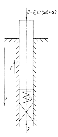
The following assumptions were adopted in the computation diagram for sinking (using the purely plastic model for ground resistance) illustrated in Fig. 3 and in the mathematical model underlying it:
- the pile constitutes an absolutely solid body;
- the ground surrounding the pile is immobile;
- there is a dry friction force acting between the side walls of the pile and the ground;
- the frontal resistance of the ground at penetration of the pile is constant over the course of the vibration period under consideration;
- the vibrator acts on the pile with a force
.
We shall pause to justify the assumptions adopted.
Experimental research has established that the amplitude of the vibrations 
To illustrate the above, a graph of the characteristic is presented in Fig. 4, which shows the progress of breakthrough over time during the sinking of a steel pipe whose vibration amplitude 
Direct confirmation that it is possible to view lateral ground resistance as dry friction was obtained experimentally by A. S. Golovachev from an analysis of the oscillograph waveform of the vibrations of a vibrating member in the ground. Experimental data attesting that the elastic component of lateral ground resistance is two orders of magnitude less than the plastic component exemplify the fact that the elastic component of lateral ground resistance is negligible during vibrational sinking at high speeds. As far as the viscous component of ground resistance during vibrational sinking is concerned, it is nonlinear in nature (i.e., it has a soft characteristic), as indicated in the preceding chapter, and it changes little with increases in speed even at low vibration speeds (5-10 cm/s).
When sinking elements with a small surface area on any given surface (sheet pile, steel pipe, and casing piles up to the moment at which the ground plug forms), irreversible ground deformations predominate over the forces of elastic and viscous drag, i.e., it is proper to assume that the total ground resistance for such elements is in the form of a dry frictional force.
In the vibration sinking process, the speed at which the eccentrics rotate is not constant. However, as theoretical research (by I.I. Vykhovskiy, 1969) and experimental research (by M. A. Gurin, 1972) have shown, changes in the speed of rotation of the eccentrics during vibration sinking comprise a total of about 5%, i.e., in calculations that have nothing to do with determining loads on the mechanism, specialized questions of the mechanism’s dynamics, etc., it is proper to assume that the angular speed 
Considering the assumptions made, the process of vibrational sinking corresponding to the computational diagram in Fig. 3 can be presented in the form of a piecewise linear characteristic having the stages enumerated below.
The raising stage:
 (2)
(2)
When the system is at its extreme upmost position, it can be parked if the sum of the forces acting on it (when the direction of force F changes) is negative:
![]() (3)
(3)
If it is parked, then the system begins to travel downward at moment t2:
![]() (4)
(4)
When no parking occurs, the system begins to travel downward at moment in time t1.
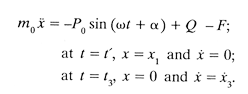
The stage in which the system travels downward until it contacts the ground plug:
 (5)
(5)
Under initial conditions (5) t’ = t1 if parking occurs and t’ = t2 if Equation (3) is fulfilled.
Stage of penetration of the plug (plastic deformations):
 (6)
(6)
The system parks during time interval from 
![]() (7)
(7)
It follows from (7) that the phase angle 
![]() (8)
(8)
To reduce the volume of calculations and to simplify analysis of the results and the mathematical modelling that will permit one to obtain the general principles governing the process of vibrational pile sinking, differential equations of motion are presented in dimensionless form, wherein all variables and parameters are dimensionless combinations of dimensional quantities:
 (9)
(9)
The results of the calculations are presented below in the form of the corresponding graphs.
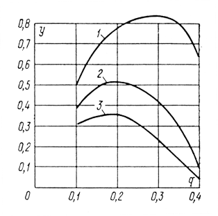
Fig. 5 shows the dimensionless settling of the pile y over the course of one cycle as a function of parameter q. It follows from analysis of the graph that there is an optimal value for the pressure exerted on the ground by the butt end of the pile, which gives maximum settling of the pile over one cycle. This result had previously been obtained experimentally and became the basis for the design of vibration sinking machines that have a sprung overweight.
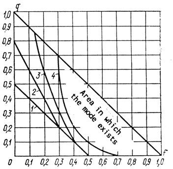
Fig. 6 shows the area in which the mode being studied exists for various values of parameters q, f, and γ. Analysis of the graph in Fig. 6 shows that the area in which the mode being studied exists is fairly broad when dimensionless frontal ground resistances are relatively large; as γ diminishes, the area in which the mode exists decreases, thus placing corresponding limitations on the selection of parameters for vibrational sinking machines.
Analysis shows that the area in which the system parks at the top is fairly broad at high lateral ground resistances 
The function relating dimensionless settling of the pile over one cycle y to dimensionless frontal ground resistance γ is nonlinear in nature, with y increasing as γ decreases, and vice versa.
The function relating dimensionless settling of the pile y to dimensionless lateral resistance f is basically almost linear in nature, with a transition to a truly nonlinear function in the area q + f ≈ 1.
As indicated above, in theoretical research the forces of frontal ground resistance can be taken as constant over the course of one cycle only in the case in which the zone of elasticity is small compared to total settling. But when developing a computational model for vibration sinking of elements with a developed frontal surface, such as piles, steel pipes with bottom ends closed, steel pipes with bottom ends open, and casing piles after the formation of the ground plug, it is necessary to take account of the elastic component of frontal ground resistance, since this is comparable to the plastic component and even exceeds it (especially at the end of the process).
The elastic-plastic model of the mechanism of ground resistance is applied when solving a specific range of subproblems in vibrational sinking. Thus, for example, the elastic-plastic model is applied in order to determine the specific depth of sinking, forces within casing piles, etc.
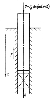
Below we consider the case in which the elastic-plastic model is used to determine the forces within casing piles being sunk by vibration (S. A. Varsanovich, 1968). The computational diagram corresponding to this method is presented in Fig. 7. In this diagram, frontal resistance R is assumed to be so large that penetration of the plug is precluded.
The differential equation for the movement of the casing, corresponding to the computational diagram in Fig. 7, has the form:
 (10, 11)
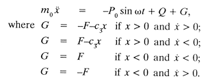
The variation in the mode of vibrations as the process parameters change can be presented in the following manner (Fig. 8).
In the case of very hard grounds 
As the compelling force P0 increases, the butt end of the column begins to break free of the ground, but the vibrations, as before, are nearly harmonic. As q and f decrease further, the harmonic process begins to distort (Fig. 8 (c)); the higher the ground’s hardness coefficient, the more rapidly this occurs. The period of movement becomes equal to T. The maximum negative amplitude Aup begins to exceed the positive amplitude Adown considerably, farther on, the process continues to deviate more and more from the harmonic shape (Fig. 8 (d)), and the amplitude of the “jump” increases sharply. As a result (Fig. 8 (e)), the period of movement becomes equal to 3T and later to 4T. Such processes are possible when q and f are quite small and the ground is sufficiently hard.
Analysis of the relationship between the maximum ground deformation values 

Even very early experiments showed that in order to extract a vibrating body from the ground a force only slightly greater than the force of gravity on the element being extracted is sufficient. The theory of vibrational extraction (Yu. O. Neymark, 1952), based on a simplified diagram, permits determination of the effort required to withdraw a sunken element as a function of ground resistance, the vibrational parameters of the vibromachinery, and the speed of extraction.
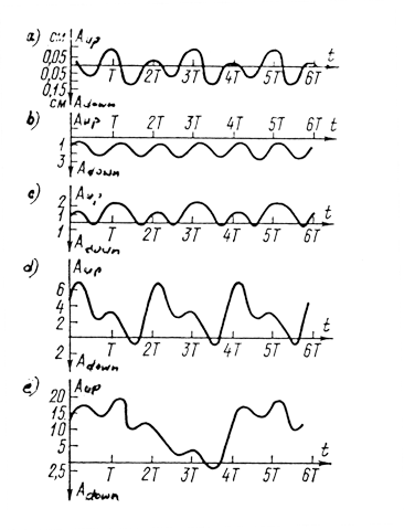
Let the element to be extracted vibrate (oscillate up and down), displacing with respect to the adjacent ground according to the formula 

If the element be taken to have a mean speed of advancement v in addition to its oscillatory motion, then, when v is positive, the graph of its speed (see Fig. 8) shifts upward a distance equal to v. On the new speed graph, the element moves upward during interval t1-t2 and downward during interval t2-t3 By now the intervals t1-t2 and t2-t3 in which the element rises and falls, are no longer equal, and hence the friction pulse over the course of a period is other than zero.
If we ignore the relationship between the dry friction force and speed, this pulse will be equal to

where time 

When this is true,
Consequently, the friction pulse over one period is equal to 
![]() (12)
(12)
The graph showing the force of resistance 


![]() (13)
(13)
It follows from formula (13) that force Gx is proportional to the speed v of the element, while the coefficient of viscous drag is equal to 

Yu. I. Neymark’s theory and the formula derived from it (13) have been borne out in practice more than once. Experience has shown that they can be used in determining the vibrational parameters and modes of vibrational extraction for various elements.
The sinking and extraction of long elements has the following experimentally established features:
- breakout of the element from the adjacent ground occurs over periods of time ranging from several seconds to several minutes (or fails to occur at all);
- when using vibration to extract pipes longer than 40 m that have resided for extended periods in the ground, an increase in the amplitude of vibrations and a considerable rise in the energy required have been observed (M. G. Tseitlin, V. V. Verstov, 1967);
- when calculating vibrational sinking or vibrational extraction, it is necessary to take account both of the breakthrough or breakout conditions and of the waveform representing the deformation of the elements once their lengths exceed as little as 20 m.
All of these experimental factors are interrelated and can only be handled within the context of a unified theory.
Described below are the vibrational extraction and vibrational sinking processes for long elements (M. G. Tseytlin, A. A. Kosheleva, 1984), with attention to their elastic deformations and using a ground resistance model that accounts for the peculiarities of the process of the vibrational extraction of long elements that have resided in the ground for an extended period.
The computational model for ground resistance was developed on the basis of an analysis of the existing experimental data, while also using analogies to the behaviour of fissured rock as described by so-called hyperstrain diagrams (V. F. Koshelev, 1979). We note that such diagrams satisfactorily approximate the known experimental data on the nature of ground resistance in the initial stage of extraction (D. D. Barkan, 1959).
The diagram showing the unit forces of resistance as a function of element displacement is shown in Fig. 11 (a), where 
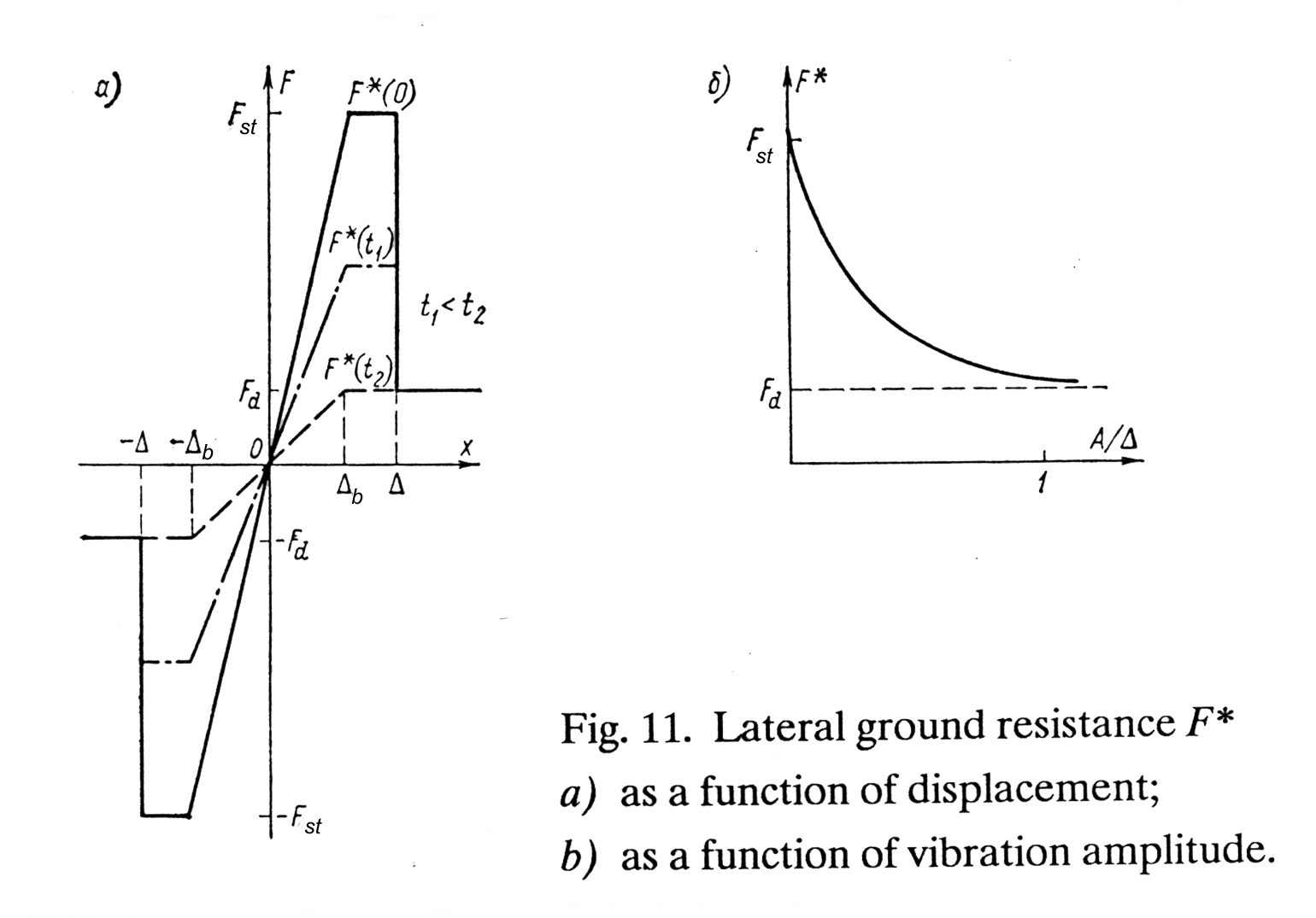
If displacement at any given moment in time exceeds 
In the breakout process, the amplitude of vibrations of the element being extracted increases over the course of time, i.e., the loads transmitted to the adjacent ground also increase, and the element’s contact with the ground is broken (the ground’s contact with the contact layer is sometimes broken as well). The fact that the breaking tension decreases exponentially as the number of cycles increases up to the breakage of contact, and the fact that the ground resistance forces simultaneously decrease exponentially as a function of acceleration (D. D. Barkan, 1959) lead to the hypothesis that

where 


Even though the internal form of Equation (14) is reminiscent of the formula derived in the works of D. D. Barkan and N. A. Preobrazhenskiy for the decrease in frictional force as a function of vibrations, it has a different physical meaning. In those works, the exponential decrease in frictional force was established as a function of vibrational acceleration in which various accelerations related to different experiments. Equation (14), however, reflects a process of gradual decrease in tenacity between the object being extracted and the ground. Here the parameters of the vibrating mechanism do not change, and acceleration increases due to an increase in the amplitude of the element’s vibrations as a result of the breakage of contact between it and the ground under the effect of the vibrations.
As is evident in Figure 11(b), breakout occurs once the amplitude of the vibrations reaches a value 

The closer the ratio of 
In the computational model, the element is a unitary elastic body in the form of a cylinder. The dissipative properties of the material are taken into account. A periodic force P0 sinωt acts on its upper butt end, as does a constant extraction or sinking effort (static overweight). The ground is considered to exert a lateral resistance to movement depending on the depth of the section. If the element exceeds the limits of elasticity, then a dry friction force acts on it; if not, this force is directly proportional to the displacement and is a viscous drag force.
The lateral resistance can be written in the following form:
 (16)
(16)
where 


The coefficient 

where F*(x, t) is the dry friction force in the plastic deformation zone; this varies over both depth and time and is defined by formula (15).
In addition to lateral resistance, a frontal ground resistance acts on the element during sinking; it is given in the form
 (17)
(17)
where 
There is a nonlinear partial differential equation that corresponds to the problem. The method of quantization permits it to be transformed into a system of ordinary differential equations, each of which is of the second order. Such a transformation is equivalent to replacing the continuous element with a discrete system in the form of concentrated masses connected one to another by weightless visco-elastic couplings. The external frictional forces are treated as if applied to the concentrated masses. The system of equations is solved as follows:
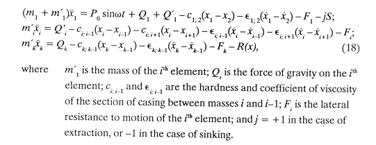
An approximate solution to system (18) can be obtained on a computer by using a Taylor series expansion. To provide a sample calculation of the vibratory extraction of casing sections that have resided in the ground for an extended period, two designs were assumed: the first had a string 100 m long and a diameter of 529 mm along its entire length; the second had a string 200 m long, a diameter of 219 mm, and was embedded 100 m deep into the ground.
Before moving on to the description of the breakout process over time when extracting casings that have resided in the ground for an extended period, we note that, previously, Fd had been assumed constant over depth. Below we consider a variant in which Fd (and Fst as well) increases in linear fashion with depth (representing an quadratic increase in resistance to extraction with depth).
The results of the calculations for the vibrational extraction of casings 100 m long agree with the available experimental data and experience in the application of vibration to the extraction from the ground of various kinds of elements that have resided in the ground for an extended period.
Fig. 12 shows the results of calculations for the vibrational extraction of a string 200 m long embedded 100 m deep into the ground. The zone of ground elasticity on the lateral surface is taken as 0.2 cm, and for breakout to occur on each section the amplitude of the vibrations should exceed a value of A = 0.5 cm. It is evident from Fig. 12 (a) that the bottom butt end of the pile began to move relative to the ground 1.84 seconds after vibrational extraction began. Fig 12 (a) shows the change in the amplitude of the vibrations at the lower butt end in the initial stage of vibrational extraction. There is an abrupt increase in the amplitude of vibrations at the moment of breakout. The damping of the vibrations along the string for this variant is shown in Fig. 12 (b). The amplitude of the vibrations of the free-standing, upper butt end exceeds the amplitude of the lower butt end by a factor of more than 35. Fig. 12 (c) shows the distribution of the maximum level of tension achieved along the length of the string during the vibrational extraction process. Like the amplitude of the vibrations, they are highly nonuniform along the length of the string and reach a maximum just below the beginning of the restraint holding the string of casings in the ground.
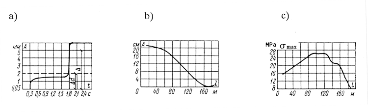

Due to the effect of the vibrations, deformations of varying sign that can become very large occur in the casing; in addition, fatigue failure of the casing material can occur over time. In the variant under consideration, the maximum power was 326 kW, with N = 197 kW after breakout.
| Parameters | Frequency, Hz | ||||||
| 7 | 8 | 11 | |||||
 | 10.0 | 10.4 | 10.4 | 6.9 | 8.5 | 6.9 | |
| , cm | 0.2 | 0.2 | 0.2 | 0.2 | 0.3 | 0.3 | |
| Δ, cm | 0.4 | 0.4 | 0.5 | 0.4 | 0.4 | 0.5 | 0.5 |
| Time to breakout, sec. | 0.35 | 0.35 | 1.85 | no breakout | |||
| A (lower end,) cm | 1.0 | 0.73 | 0.61 | 0.006 | 0.01 | 0.014 | 0.019 |
| Nmax, kW | 383 | 326 | 333 | 169 | 162 | 165 | 160 |
| Nd | 183 | 177 | 150 | — | — | — | — |
Table 2 shows the results of calculations for the vibrational extraction of a string of casings 200 m long embedded 100 m into the ground (Fd = 0.045 MPa, P0 = 250 kN, S = 200 kN, ε2 = 500 N/cm, ε1 = 45 N/cm-s, c4= 67.2 • 105 N/cm) at various operating frequencies and under varying ground conditions, from which it is evident that reducing frequency without increasing the compelling force and the static extracting effort permits one, under certain conditions, to remove a string of casings from the ground even under more difficult ground conditions (as determined by Fd and Fsi).
By analysing the results obtained it is possible to draw the following basic conclusions:
- The amplitude of vibrations of the casing being extracted or sunk varies significantly along its length.
- Breakthrough or breakout takes place at a different time for different sections of the casing.
- Appropriate selection of the operating frequency, with account taken of the elasticity of the casings, opens the possibility of extracting or sinking long elements without significantly increasing the compelling or static forces.
- 4. In those cases in which design and technological conditions permit it, it is advantageous to situate the exciter within casings of large diameter (for example, at the bottom).
The calculation method given above opens the possibility of making a justified choice of the parameters for the vibrational sinking or extraction of long elements. This method can be applied particularly effectively when developing vibrational sinking machinery with variable parameters. It permits one to determine the preferable frequency ranges and on that basis to develop an optimal algorithm for regulating the operating frequency.


6 thoughts on “Immersion and Extraction by Longitudinal Oscillations”