
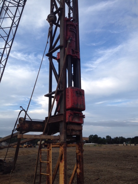
The issue of slide bars, full and short stroking and blow rate have always been central to the proper “certification” and operation of Vulcan hammers. In this post we will take a “bare bones,” basic approach to the dynamics of the problem with the most basic automatic hammer of all: a single-acting air/steam hammer, in this case the venerable Vulcan #1 (shown above.)
The basic data we’ll need:
- Ram Weight W = 5000 lb.
- Stroke s = 3 ft.
- Operating Pressure p = 80 psig (the “g” is important because it is a gauge pressure, as the air or steam pushes upward the atmosphere on the other side pushes downward, this is taken into account with the gauge pressure.)
- Net Area of Piston A = 133.51 sq. in. (the area against which the pressure operates, excluding the piston rod in the middle.)
- Acceleration due to gravity gc = 32.2 ft/sec2. This means that the mass of the ram is 5000/32.2 = 155.3 slugs.
The assumptions we’ll use.
- We will not consider the effects of friction or back pressure on the ram or the piston rod. That includes things such as the ram-column, packing and piston ring friction, or valve induced losses. Vulcan included these effects in the “closed form” solution (similar to what will be presented here) it actually used in design and later with numerical methods such as those used in the Valve Loss Study and the Single-Compound Hammer.
- No expansion of the air or steam during operation is assumed. Vulcan’s competitor Menck used to consider that their explicitly expansive use of the steam was an advantage, but the truth is that the air or steam in the system is constantly expanding anyway. Vulcan used it expansively by design in the California series of hammers.
- No effect of the dashpot (gas spring) at the top of the stroke will be included. This too entered into Vulcan’s own slide bar setting routines.
- The hammer is assumed to be operating plumb (vertical) and not in batter (at an angle with the vertical.)
- There is no rebound energy at the start of the cycle. This is important; Vulcan never assumed rebound velocity from the pile for the hammer to achieve full stroke with its conventional hammers. This made starting them easier; diesel hammers, for example, require some rebound to achieve full stroke.
Basic Hammer Cycle Calculations
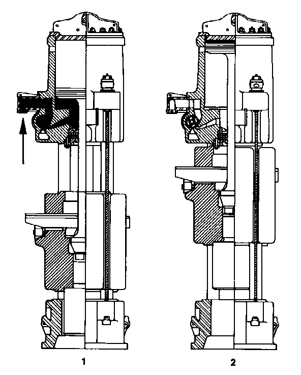
As explained in its later onshore literature, the single-acting cycle is as follows:
Concerning the operation of the hammers themselves, the cycle begins at impact, the valve is rotated in such a way as to admit steam or air into the cylinder and below the piston. This accelerates the ram upward as shown in View 1. This continues until the exhaust wedge on the slide bar actuates the trip and rotates the valve to close off the steam or air inlet and opens the area of the cylinder below the piston to the atmosphere where the compressed air or steam is exhausted. The ram continues its free rise upward, decelerating with gravity until the top of the piston passes the relief ports and closes in the dashpot at the top of the cylinder. This trapped air, shown in View 2, compresses and brings the rising ram to a halt. The ram then makes a free drop to impact. Shortly before impact the intake wedge rotates the valve to admit steam or air to the cylinder and the cycle starts once again.
With the assumptions above, there are three phases to the operating cycle:
- Power upstroke, where the pressure on the lower side of the piston creates a net upward force on the ram.
- Glide upstroke, where the valve turns over and the pressure goes to atmospheric, which means that the only net force on the ram is downward (the ram weight.) The ram comes to a stop at full stroke (it can be short stroked as well.)
- Glide downstroke, where the ram falls to impact. Once the ram’s energy is imparted to the pile, the cycle begins again.
Solving the Equations of Motion
For all three phases, the basic equation of motion is

In this case, F is the force on the ram other than the weight. For Phase 1, it is the upward pressure of the air or steam, F = pA. For Phases 2 and 3, it is zero.
Integrating twice and determining the constants of integration,

For each phase, the time is reset to zero at the beginning of the phase. This makes piecing the whole cycle at the end a little trickier but makes the math a little simpler to express. For each phase x(t) is the displacement from the starting point of the phase. Phase 1 starts at the impact point; Phase 2 starts at the air/steam cut-off point and Phase 3 starts at the top of the stroke and ends at the impact point.
After some algebra, the equations for Phase 1:


Equations for Phase 2:


The velocity v2 is the velocity at the cut-off point and x2 is the height of the cut-off point.
Equations for Phase 3:


At this point we need to determine the cut-off point x2. We could do this by solving the equations of Phases 1 and 2 simultaneously but there is an easier way: using an energy method. In this case we note that the energy imparted to the ram by the pressurised air or steam must equal the energy that is expended at impact (the rated striking energy of the hammer.) This means that

Solving for x2,

We can solve for v2 by noting that the potential energy required to move the ram from the cut-off point to the top of the stroke is equal to the kinetic energy at the cut-off point, or

Solving for v2,

It is also possible to solve for the time duration of each phase using the equations, but again there is an easier way. We do this by noting that all of the forces on the ram–and by extensions the accelerations (see Equations (3c), (4c) and (5c))–are constant for each phase. Let us look at the diagram below, from Movnin and Izraelit (1970), which will also help us to understand graphing the solution of this problem.
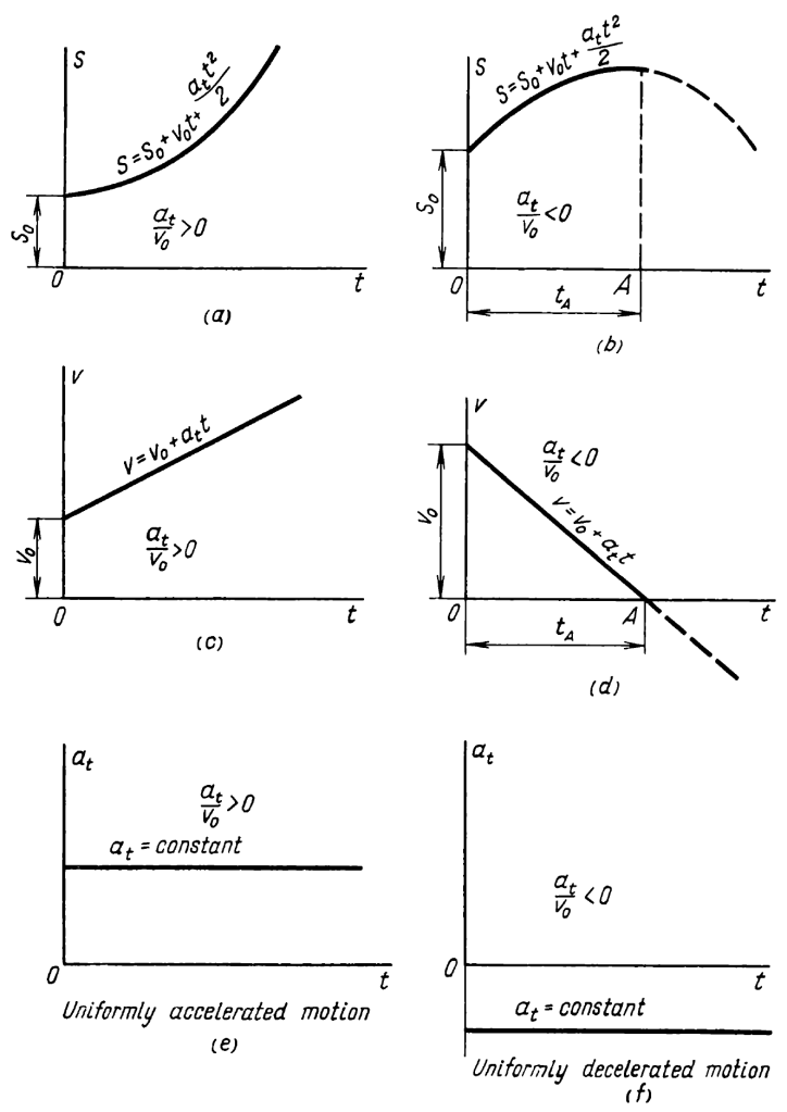
We note that, for uniformly accelerated or decelerated motion, the velocity varies in a linear way with time. For a uniform velocity,

With the type of motion shown above, in a time period where the acceleration is constant, the average velocity is half of the peak velocity vf at the end of the time period (or beginning for decelerated motion) tf, or

Solving for the time at the end of the period,

Applying this equation to each of the periods yields values for the time of each phase:


The total cycle time is

and the blows per minute is computed from

It is worth noting that, if the result from Equation (13c) is substituted into Equation (5b), the impact velocity results, which is

It is negative because we assumed upward to be positive. A geotechnical engineer would have done the opposite.
Presenting the Results
If we substitute the parameters given at the start into the equations, the following results take place:
- Cut-off Point x2 = 1.404′ (Equation (7))
- Cut-off Velocity v2 = 10.14 ft/sec (Equation (9))
- Impact Velocity v4 = 13.9 ft/sec (Equation (16), this is also standard for any 3′ stroke hammer)
- Phase 1 time t1 = 0.277 sec. (Equation (13a))
- Phase 2 time t2 = 0.315 sec. (Equation (13b))
- Phase 3 time t3 = 0.432 sec. (Equation (13c))
- Total cycle time ttot = 1.024 sec. (Equation (14))
- Blows per Minute = 58.6 (Equation (15))
Some comments on these results are as follows:
- The cut-off point is nearly half the stroke. This is a “standard” which Vulcan followed for much of its history. Raymond did not; many of their cut-off points were 65-75% of the stroke, which reduced the blow rate of the hammer but allowed smaller cylinders to be used with larger ram weights (such as the 60X.) Vulcan also varied from its earlier practice in its later years, especially with the 5′ stroke offshore hammers.
- The net upward acceleration is around 1 g, the net downward acceleration is – 1 g (the acceleration due to gravity.) Designing the hammer this way is in fact what put the cut-off point where it is. It requires the net force on the piston during power upstroke to be about twice the ram weight.
- This requirement also makes the balance pressure (the pressure at which the air or steam force on the piston is equal to the ram weight, above which the ram will move upward) about half the operating pressure. Reducing the ratio of the upward force of the air or steam with the ram weight increases the balance pressure to become closer to the operating pressure. This in turn reduces the “play” that the operator has in adjusting the stroke with the pressure.
- The blow rate is nearly the 60 BPM that is characteristic of 3′ stroke hammers. Frictional and other losses, along with the dashpot at the top of the stroke, required that Vulcan raise the cut-off point, which (along with rebound) speeded up the hammer. The variation in blow rate with the cut-off point is the central reason why Vulcan hammers cannot use a device like the Saximeter to estimate energy output.
- For many years changing the operating pressure to adjust the stroke was frowned upon by Vulcan, which led to the development of the Vari-Cycle. It was also impossible to achieve half or lower strokes without changing the cut-off point because of the limitation of the balance pressure.
The diagram above from Movnin and Izraelit (1970) suggests that we can plot the acceleration, displacement and velocity in a similar manner. It would be helpful to be able to plot them on a single plot, and this is accomplished by normalising (or non-dimensionalising) the results. We do this by dividing each by a characteristic limit value, using the following equations for normalised displacement, velocity and acceleration respectively as follows:


The resulting plot is below.
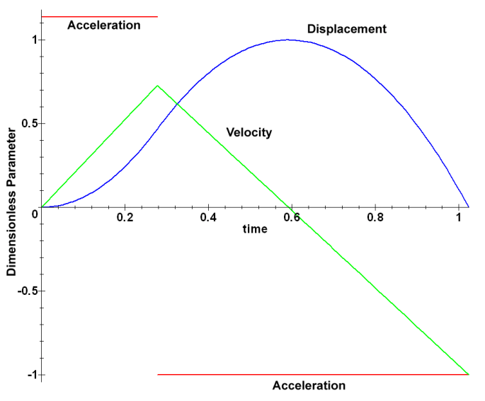
- The acceleration has only two values: power upstroke and the rest of the cycle. Note that they, as noted, are nearly mirror images of each other.
- The velocity increases linearly to the cut off point and then decreases, achieving zero at the top of the stroke and decreasing further to impact.
- The displacement starts at zero, comes to a maximum at the top of the stroke and returns to zero at impact.
As noted earlier, Vulcan’s actual computations took into consideration other factors. But the Vulcan single-acting hammer is a simple machine, and this simple method of design was central to making it possible. Differential acting hammers have a similar cycle analysis but the actual implementation is more complicated.


3 thoughts on “The Basics of Setting the Cut-Off Point for a Vulcan Single-Acting Hammer”