
Editor’s Note: This monograph was produced by Petro-Dynamics, Lafayette, LA. It was undated; it probably was produced in the early 1980’s and was disseminated at the Offshore Technology Conference. Although it is around four decades old, the basic concepts of the Case Method and CAPWAP are still in use today.
One thing that surprises is that the pile mass 
The original WEAP program is discussed (and the source code available for download) here. As was the case with the original monograph, all of the graphs are at the end. They may look primitive but with the technology of the time they took quite a lot of effort to produce.
Dynamic formulas were commonly employed to determine dynamic bearing capacity of piles during the driving operation. Numerous such formulas are available. The most common ones are the Engineering news record, Hiley’s, Rankine’s, Chellis’, etc. These formulas have been severely criticized because they incorporated empirical factors whose roots cannot be traced. As a result their validity and applicability are questioned.
This problem persisted for a long time. Finally the Ohio Department of Transportation and Federal Highway Administration, understanding the seriousness of the problem sponsored series of research projects at Case Western Reserve University to study the dynamic behaviors of piles and pile driving hammer performances during the driving operation.
The research emphasis can be broken down into three categories
- Investigation of the reliable mathematical approach to the problem–Traveling wave solution of the one dimensional linear equation was found to be the most appropriate to the prevailing problem. As a result the Case Method capacity determination was developed.
- Method of data acquisition: Electronic equipment such as reusable transducers and a data recording system was devised.
- Invention of a system for data processing and analysis: A Pile Driving Analyzer (Portable computer) was built to process and analyze the data right at the job site.
The benefits from the research are tremendous. It has opened a new era in the field of pile driving both on land and offshore. A few of the benefits which are currently performed routinely are as follows:
I. Pile Capacity Determination
A procedure known as the Case Method was developed to determine the pile capacity dynamically for every hammer blow as the pile penetrates through different soil strata. This is possible by electronically measuring force and acceleration of the pile using strain transducers and accelerometers attached to the pile top. The resistance as computed by the Case Method is expressed as follows:


The dynamic resistance better known as damping force is obtained from

where J is a damping constant which is dependent on the soil type and 
where 


The static resistance is computed automatically from the above expression by the Pile Driving Analyzer and results are printed out for every blow. During the research projects a correlation study of dynamic bearing capacity with that of the capacity obtained statically (such as from load test) were found to be in an excellent agreement.
II. Control Driving Stresses and Damage Detection:
In most cases, piles are subject to high stresses during driving. It is important to control and watch the driving operation very closely. The forces delivered to the pile are computed automatically from the strain readings by a Pile Driving Analyzer and from these forces,the stresses the pile is subject to by every hammer blow is calculated. Thus,it is possible to control the hammer throttle settings or stream pressures if the damage from high driving stresses is likely.
The structural pile damage at any other location along the pile length can be detected by closely watching the force and velocity records on the screen of an oscilloscope (an integral part of the dynamic measuring system).
High tensile stresses are prevalent in concrete piles which might cause structural damage at certain locations along the pile length.
If damage is detected from the observation of force and velocity records at an earlier stage of driving transducers may be mounted at that location and stresses investigated as a function of cushion, cap, helmet or even different hammer in an effort to reduce the stresses and continue driving.
In piles already driven to required penetration the Pile Driving Analyzer is effectively used to detect structural damage of the pile by restriking them with only few blows. A long term set up capacity can also be determined from restriking information. This procedure has been used routinely especially on concrete piles where cracks from high tensile stresses either at the pile splices or in the pile material are likely.
III. Data Acquisition Methods and Their Permanent Storage:
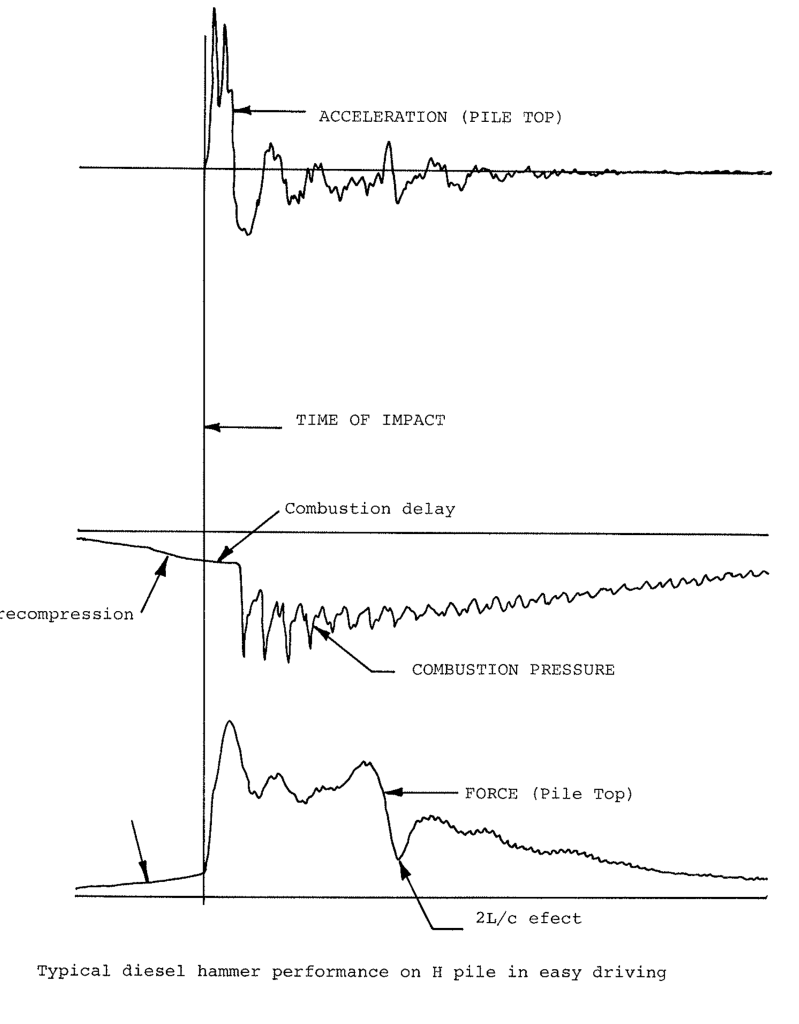
Electronic equipment namely strain transducers and accelerometers are used to measure the strain and acceleration of the pile top. The strain reading is automatically converted to force using the cross sectional area and modulus of elasticity of the pile. The acceleration and force records are continuously displayed on an oscilloscope to check the quality of the records. The acceleration record is integrated to obtain velocity. Necessary computations of force, pile capacity, transferred energy, maximum velocity, maximum acceleration and other quantities are performed automatically by a Pile Driving Analyzer right at the job site and results printed out on paper tapes. Both force and acceleration records are stored on analog magnetic tape using a portable multi-channel tape recorder. The information recorded is later processed at the office using larger computer. The tapes are then kept as a permanent record to be reached only when need arises.
IV. Hammer Inspection:
The proper performance of hammers is very important in pile driving. The hammer should be capable of embedding the pile to its proper design elevation safely without causing damage to the pile. Hammers are generally selected by their rated energies as defined by hammer manufacturers. All hammers do not deliver their full available energy to the pile. A substantial amount is lost within the hammer system during impacting. Impacting losses results from heat, friction, combustion inefficiencies such as pre-ignition, ram impact velocity, and inelastic collisions in drive cap assembly. Only a certain percentage of the rated hammer energy is delivered to the pile. If a poorly performing hammer is used in driving a pile a high blow count is reached and thereby get to a refusal criteria at the early stage of driving. This, of course, is misleading especially when costly alternatives such as drilling, jetting or changing to a larger hammer are to be employed.
In order to define refusal the hammer energy delivered to the pile should be taken into account. The energy delivered to the pile is calculated from the force and velocity records measured at the top of the pile during driving. The maximum energy is computed by a Pile Driving Analyzer from the expression below.

where energy, 


V. Driveability Survey:
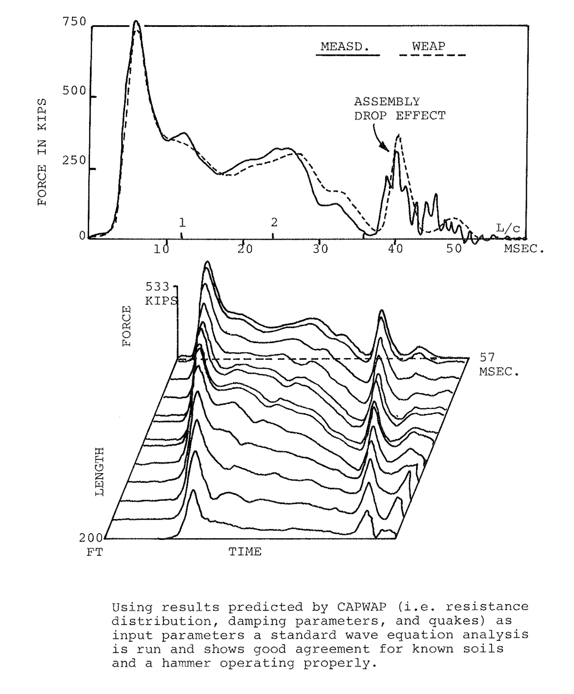
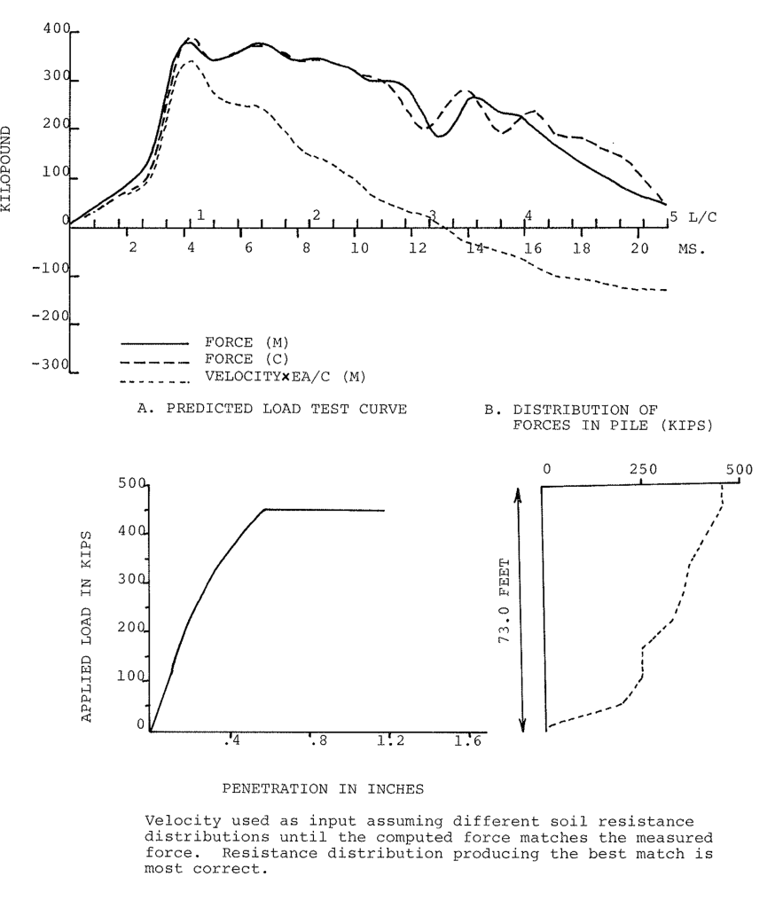
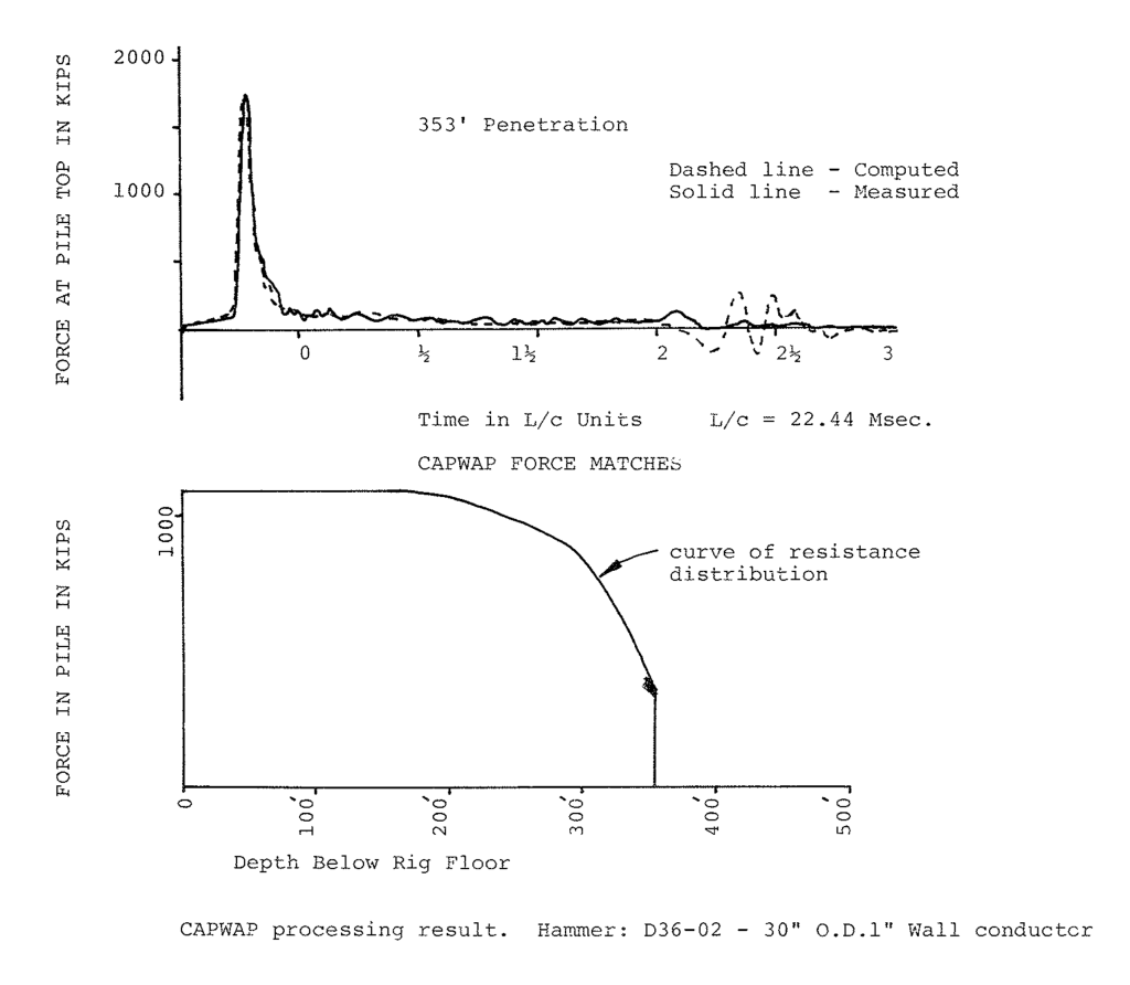
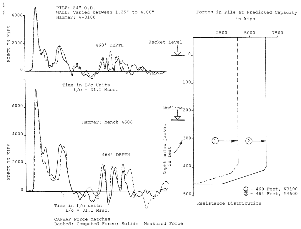
A survey of the driveability of conductor piles is routinely performed by Petro-Dynamics, Inc. from exploration rigs. The force and acceleration records are measured electronically on the conductor pipe while the rig is out for an exploration. These records are analyzed in relation to the type of hammer to be used, the soil type and the resistance to be encountered during the actual driving operation of conductors and main structural legs. This is possible by the use of a computer program known as CAPWAP (Case Pile Wave Analysis Program). In the program the measured velocity obtained by integration of the acceleration record is taken as an input quantity. From this input and an assumed set of soil resistance forces, the pile top force can be computed using a lumped mass-spring system as is commonly used in all pile wave equation programs. By adjusting the resistance forces and balancing them between static and dynamic resistances it is possible to adjust the computed force so that it agrees with the measured force record. The CAPWAP program performs this function automatically.
From this analysis a correct soil parameters can be drawn without running the actual soil boring. Another important feature of the program is that it is possible to estimate the skin-distribution and toe bearing. The portion along the length of the pile, where the skin resistance distribution is the greatest can be located.
The soil constants drawn from CAPWAP analysis are used as an input in the conventional wave equation analysis. These are two recent wave equation programs, The TTI program and WEAP (Wave Equation Analysis Program). Both programs do an adequate job for air steam hammers. The WEAP program does a more realistic analysis in modelling the thermodynamic process of diesel hammers. The WEAP program is at our disposal. Using this program and the soil constant obtained from CAPWAP analysis it is possible to arrive at the size of hammer to be used and blow count to be expected during driving. Therefore, it suffices to say that driveability survey helps a great deal in planning the driving operation.
For any further information and assistance regarding the Pile Driving Analyzer, dynamic measurement, analysis of conductor, and structural leg piles, please feel free to contact us.
PETRO-DYNAMICS, INC.
P. O. BOX 53526
LAFAYETTE, LOUISIANA
PHONE: 318/837-1181


4 thoughts on “Dynamic Measurement of Piles”