

Although Vulcan was best known for products based on sand castings, many of Vulcan products–especially those produced by the Special Products Division–were fabricated. An important operation in fabrication is plate bending. Although plate bending is usually associated with sheet metal formation like Vulcan’s vibratory power packs, Vulcan also bent plate which is thicker than normal sheet metal. An example of a bent plate part is the motor guard for the 2300/2300L/2300A vibratory hammer, shown in the photo above.
One question which is hard to get an answer for is “how small does the bending radius have to be before the plate breaks?” This piece attempts to furnish an answer for that. An interesting study of this was done by Datsko and Yang (1959), and that forms the basis for this piece, although the solution presented needs to be used with care.
Let’s start by defining some nomenclature.
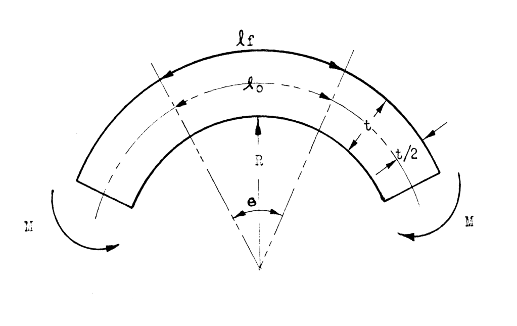
As is the case with any bending, the process of bending induces a moment in the plate around a bending mandrel. The concept is to bend a plate of thickness 

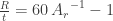
Datsko and Yang (1959) discovered that the minimum bend radius could be determined using one parameter: the reduction in area 
First, for values of 


Second, for values of 

The “trout in the milk” for the equations is that the values aren’t the same when 


Third, Datsko and Yang (1959) also recommend “from laboratory experience” that this equation
“…is a very satisfactory relationship for the ductile materials that do have a shift in the position of the neutral axis.”
The three relationships are plotted below.

Let’s do an example using Equation (3). Consider an ASTM A514 Gr. B (a “T1” type steel) with a yield strength of 100 ksi (689 MPa) and a reduction of area of 40%. Direct substitution in to Equation (3) yields 

The key problem here is whether the steel has the reduction in area the “typical” values indicate. In some cases it is difficult to obtain the reduction in area. In others the steel is not properly tempered and thus does not have the ductility one should expect. Defensive design in these cases is crucial. Although Datsko and Yang (1959) considered non-ferrous materials, Vulcan did not widely use these in its products, especially in its fabricated ones. The actual strength of these bent corners is also an open question.
The method described here give a “theoretical minimum” to the bend radius, but should be used with a generous “factor of safety” to insure that bent plate areas retain their material integrity after bending.
References
Datsko, J., and Yang, C.T. (1959) “Correlation of Bendability of Materials With Their Tensile Properties.” The University of Michigan Industry Program of the College of Engineering. Report IP-401, November.

