
L.V. Erofeev, VNIIstroidormash
V.A. Nifontov, VNIIstroidormash
D.C. Warrington, Vulcan Iron Works Inc.
Notes
- This article first appeared in the First May Issue 1993 of Pile Buck. It is reproduced here with a few changes. .
- Additional information (including some detailed theory on diesel hammer operation) can be found in the article Diesel Hammers, which was written by one of the authors of this article.
- The complete history of Vulcan’s dealings with the Russians concerning the diesel hammers, including their importation of diesel hammers from various Russian sources and the commissioning of a new series of diesel hammer designs, can be found here.
Introduction
Pile foundations have been around for quite a long time, and to many people justification seems superfluous. Nevertheless, given the speed of technology advance and the technical amnesia this can create, it is worthwhile to stop and remind ourselves that pile foundations have both economic value and technical appeal. The whole process is an enormously complex one in all of its aspects, whether we consider the mechanics of the impact or the transfer of the load from the pile into the soil and the soil’s response to it.
In Russia, a country that is admittedly ready made for deep foundations, pile foundations are the most widespread foundations for buildings and structures in civil, military, industrial and hydrotechnical construction because their use instead of ring foundations makes it possible to significantly reduce amounts of earth moving works, to reduce labour consumption by 50%, and concrete consumption by 33-50%. Pile foundations additionally provide building settlement that is both lower and more uniform than ring foundations. This fact is especially important in the construction of block-type and large panel buildings, such as the high rise apartment buildings one normally associates with Russia.
To drive these piles and thus reap the benefits of these advantages, the most widespread machines for driving piles are diesel hammers. Their main advantages are 1) independence from external power sources such as steam boilers, air compressors, generators, or hydraulic power packs, 2) high productivity, 3) simplicity and convenience of operation, and 4)relatively low price of manufacturing. Eighty percent (80%) of all piling works in Russia are carried out by diesel hammers. Each diesel hammer during a year fulfils piling works which cost forty (40) times as much as the price of the diesel hammer itself.
Overview and Development of Russian Diesel Hammers
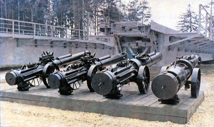
The principle of operation of all diesel hammers is based on the two stroke internal combustion engine with compression ignition. The impact force of a diesel hammer is the result of both the direct impact of the ram on the anvil and the pressure of air-fuel combustion. Diesel hammers are divided by their design into two types, tubular and rod type. Rod type diesel hammers, as shown in Figure 1, are used for driving light concrete and sheet piles. Tubular diesel hammers are mostly used for driving medium and heavy concrete and steel piles. The high driving capacity of tubular diesel hammers is gained because of their relatively small compression ratio (CR = 15) and high stroke (s = 3000-3300mm) in comparison with rod type diesel hammers (CR = 25-28 s = 2000-2500mm). As tubular diesel hammers are the most widespread diesel hammers both in Russia and elsewhere, this paper is concerned with tubular diesel hammers.
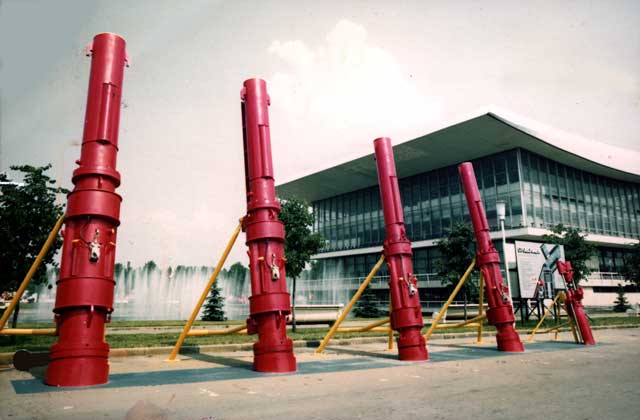
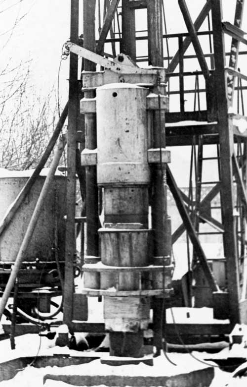
Under normal circumstances, the total annual output of tubular diesel hammers in Russia is about 1,500 units. Diesel hammers for civil needs are produced by three manufacturers. The division “SZSM” is the main manufacturer of diesel hammers in Russia. It produces diesel hammers in five (5) sizes with ram masses as shown in Table 1.
| Model | SP-75 | SP-76 | SP-77 | SP-78 | SP-79 |
| Impact portion mass,kg | 1250 | 1800 | 2500 | 3500 | 5000 |
| Photograph Figure | 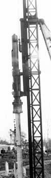 Figure 2 | 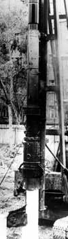 Figure 3 | 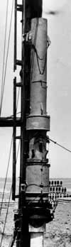 Figure 4 | 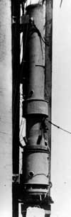 Figure 5 | 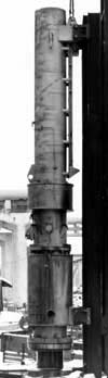 Figure 6 Figure 6 |
| Maximum Impact energy,kJ | 40 | 56 | 82 | 115 | 160 |
| Frequency of Impacts, Hz | 0.7 (42 BPM) | 0.7 (42 BPM) | 0.7 (42 BPM) | 0.7 (42 BPM) | 0.7 (42 BPM) |
| Size of Square Concrete Piles to be Driven, cm | 30 | 30 | 35 | 40 | 40 |
| Length of Pile to be Driven, m | 8 | 12 | 16 | 20 | 24 |
| Fuel Consumption, kg/hr | 6.1 | 6.4 | 11.8 | 17.0 | 19.0 |
| Oil Consumption, kg/hr | 1.3 | 1.3 | 1.3 | 1.3 | 1.3 |
| Hammer Total Mass, kg | 2700 | 3850 | 5500 | 7700 | 10000 |
| Cylinder Diameter, mm | 300 | 345 | 400 | 470 | 470 |
| Working Stroke, mm (distance from impact to opening of exhaust ports) | 285 | 310 | 420 | 385 | 680 |
| Type of cooling system | Water cooled | Water cooled | Water cooled | Water cooled | Water cooled |
These were originally designed by NPO “VNIIstroidormash” based upon the principle of geometrical similarity; the general layout of these machines is shown in Figure 7. The main feature of these diesel hammers is the presence of the interchangeable cylinder (5) with the water cooling system. The replacement of this cylinder by a new one (which is included in the delivery set) is carried out in case the construction workers manage to wear 1 mm off of the inner walls of the cylinder, a parameter gleaned from sources outside of Russia. In this case there is no necessity to send the hammer to a repair shop. The technical data for these hammers is shown in Table 1.
| 1 – upper cylinder 2 – piston 3 – fuel tank 4 – fuel pump 5 – lower cylinder 6 – anvil block 7 – oil hose for anvil block lubrication 8 – water tank | 9 – oil pump 10- oil tank 11- crab 12- crab guide 13- oil hose for ram rings lubrication 14- filling throat plug 15- drain throat plug |
While the original design was basically successful in both production and use, there were a few difficulties. The first concerned the alignment of the cylinders. The interchangeable cylinder contains two flange joints and sometimes during assembly it is very difficult to obtain proper axial precision. Also, the bolts holding the cylinders together would not stay tight and in some cases its life was too short. In response to these problems “VNIIstroidormash” designed the “A” series of hammers, with designations SP-75A, SP-76A, etc.. The technical specification of each of the machines is the same as the earlier design however, in the modified models there is only one flange joint between working and upper cylinder. This feature makes it possible to obtain better axial precision during assembly. The interchangeable cylinder is made of wear resistant material in addition to this, an additional oil pipe line was installed and lubrication oil from the pump was supplied not only to anvil compression rings but to the upper cylinder too. The bolted joints were changed to clamped ones bench tests confirmed the advantage of this type of joint.
Operation
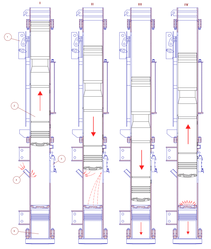
The tubular diesel hammer operates as follows (Figure 8): the piston with the assistance of crab (Russian name for the starting device) driven from the winch of the pile driving rig (in common with machines operated in many other places, Russian hammers are operated from a dedicated pile driving rig) is raised to an upper position at which it is released by the crab and falls down under its own weight. Before the bottom of the ram passes the exhaust ports the piston pushes the fuel pump lever and fuel from the pump is supplied to the spherical recess of the anvil. At the bottom of the stroke the piston impacts the anvil. The energy of impact is divided between fuel vaporization and its mixing with heated air and driving of the pile. After a short period of time the air-fuel mixture is ignited and due to the pressure of the expanding exhaust gases the piston is raised up and additional driving impulse is transmitted to the pile.
| Hammer Parts: 1 – crab 2 – piston 3 – fuel pump 4 – inlet 5 – cylinder 6 – anvil | Stages in Cycle: I – ram up (start), scavenging II – termination of scavenging, fuel feed III – termination of compression stroke, blow delivered on anvil block, fuel combustion IV – termination of fuel combustion, exhaust, beginning of scavenging |
Water cooled diesel hammers may operate for a long time at ambient temperatures greater than +40 deg. C without overheating. The heat removal may be increased by a circulation evaporation cooling system use in diesel hammer design. This system consists of separate pipes which are filled with cooling water. These pipes are located on the outside of the lower cylinder connected in lower parts with each other by a circle tank located at the level of the combustion chamber. During operation cooling water is heated very intensively in the tank and begins to circulate inside vertical pipes, providing uniform lower cylinder cooling. Cooling surface in the case of this type of cooling system use is rather large so the operation of diesel hammer at high ambient temperatures is more efficient because of better heat removal. In case of ambient temperatures below freezing water from the cooling system is removed via a screwed plug located at the bottom of the circle tank, and the hammer operates like an air cooled hammer, but with the air circulation through the openings at the upper part of vertical pipes.
Construction
Figure 7 shows a general view of the SP-79 diesel hammer, which is typical of the hammers shown in Table 1. The hammer itself comprises a lower (working) cylinder (5), upper cylinder (1, guide pipe), piston (2, impact portion), anvil, fuel pump (4) and crab (11). The lower cylinder is located in the area of maximum internal surface wear and is of short height (not more than 1/3 height of diesel hammer) and very simple design. The processes of compression, mixing, combustion, expansion of exhaust gases and filling with fresh air charge take place in the lower cylinder. The upper cylinder is completed with oil tanks, fuel tanks and pumps, and crab with guide (12). For attachment of hammer lifting cables, two lifting hooks (ears) are welded on the outside of the top of the upper cylinder. At the bottom of the upper cylinder there is the flange for a bolted connection with working cylinder flange. The fuel tank (3) and pump are connected with a flexible hose, which is attached to the outside of the cylinders. To the lower flange of working cylinder the anvil ring is attached by screws to hold the anvil during lowering. At the middle part of the cylinder there are located detachable guides to connect hammer with the leader of the pile driving rig. Piston (2) is located inside the cylinders. Water cooling system comprises water tank (8), located at the level of combustion chamber, with filling (14) and drain (15) ports.
1 – drive lever
2 – plunger
3 – ball valve
4 – intake ball valve
5 – adjusting lever
The low pressure plunger type fuel pump is shown in Figure 9, and is intended for fuel supply to the combustion chamber. It is attached to the cylinder with studs and nuts, and it contains a rotatable lever to adjust fuel feed in a continuously variable fashion. A special clamp welded to the cylinder protects the fuel pump from damage. The fuel pump operates as follows: The piston presses plunger (2) via driving lever (1). The fuel pump is thus pressurized the inlet valve of the pump is closed and fuel accumulated in the pump is discharged via ball valve (3) to the combustion chamber. When the plunger moves back to the initial position valve (3) begins to close, valve (4) opens and the fuel pump fills with fuel via the flexible hose from the fuel tank. There exists continuously adjustable fuel feed in the fuel pump. When the adjusting lever (5) is rotated clockwise the amount of fuel to be supplied to the combustion chamber is decreased and when rotated anticlockwise it is increased.
Returning to Figure 7, the lubrication system of tubular diesel hammer consists of oil tank (10), attached to the guide pipe, from which oil with the assistance of oil pump (9) is supplied via flexible hoses (7) and (13) to the lower anvil ring and to guide pipe to lubricate piston compression rings. The oil pump design and principle of operation is similar to the fuel pump, and its general construction is shown in Figure 10.
The crab (see Figure 11) assists the starting of the diesel hammer. It is installed on guide located at the upper cylinder of the hammer. When the crab is lowered along the guides, its linkage engages the piston with hook (1). When the crab is lifted up to the limiting position of the cock and release lever (2) the hook disengages the piston and it falls down under its own weight.
1 – hook
2 – cock and release lever
Tubular diesel hammers are completed with pile caps which are installed between anvil and pile, as shown in Figure 12. These caps provide force distribution upon the pile top. The pile cap must provide pile driving into hard soils without pile head damage. A rod is screwed into the lower end of the anvil. The purpose of this rod is to properly center the pile top with the hammer. During driving the rod is squeezed into a wooden washer plate of the pile cap under the weight of the hammer. The anvil is surrounded with 2 pairs of semirings, upper and lower. These semirings prevent contact surfaces from wear and increase the durability of the parts. The upper part of the piston is bored for oil tank with screwed cover. This cover has a screwed hole for small plug to be screwed during operation or ring bolt to be screwed during mounting and dismounting in case of maintenance or repair works.
In addition to the water cooled hammers described here, tubular diesel hammers are produced with air cooling systems. These hammers are similar to the water cooled hammers in their construction except that the water tank is replaced by fins which assist the hammer’s convective cooling. During intensive diesel hammer operation, especially in case of driving heavy piles into hard soils or in case of ambient temperature above +30 deg. C and diesel hammer operation for two (2) shifts a day, the lower cylinder temperature be very high. In this case the stroke is decreased, which decreases the energy per blow.
Conclusion
Diesel hammers were developed to be an economical tool for the installation of pile foundations, and Russian diesel hammers represent a successful fulfillment of that initial purpose. They are designed according to established principles and manufactured to be simple of operate and service. They are viable tools in the real world of foundation construction.


18 thoughts on “Russian Diesel Hammers”