
The concept of using sea water as the motive fluid for an underwater hydraulic hammer is an intriguing one. Doing so has two key advantages:
- Eliminates the use of hydraulic fluid, which can be environmentally hazardous (depends on the type); and
- Eliminates the need for a return line, irrespective of whether the pump/power pack is on the surface or underwater.
Vulcan initiated two efforts in the production of such a unit.
The first was a design set forth by John Lerch, Vulcan designer in the 1970’s. His concept for a sea water hammer is detailed here as a patent proposal. The proposal was not pursued.
The second was Vulcan’s effort with its Russian associates. This concept was developed in 1994-5; one of the developers was Dmitri A. Trifonov-Yakovlev, son of Alexandr Sergeivich Yakovlev, founder and designer for the Yak aircraft design bureau. Unfortunately, Vulcan’s difficulties prevented its commercialisation. However, a patent was obtained on it (U.S. Patent 5,662,175).
The rest of this page will concentrate on the latter concept.
Purpose of the unit
The use of underwater pile hammers for the installation of foundations for deep-water offshore oil platforms dates from the 1970’s. Most of the hammers used in this application are hydraulically powered. The hammer case (they are always of closed construction) is evacuated using compressed air and the hammer is lowered onto the pile for driving.
Although these hammers have been generally successful, there are two major drawbacks.
The first concerns the possibility of spillage of hydraulic oil by the breaking of the hose or couplings or simple leakage. This is environmentally unacceptable in many jurisdictions. One obvious solution to this problem is to use vegetable or other “environmentally safe” oils; this is common with vibratory hammers. However in some applications even this type of contamination is unacceptable (food preparation, for example) and others (such as ours) the governing authorities (such as the U.S. Coast Guard) have systematically refused to enforce the laws as written and require cleaning up “safe” fluids, even edible ones.
The second concerns the evacuation of the “diving bell” for the unit, which adds to the complexity of the hammer.
To address these concerns, the sea water hammer was developed. It is in reality a special type of hydraulic impact hammer and is primarily intended for driving into the soil steel tubular piles in onshore and offshore conditions. The main fundamental differences between a sea water hammer and more conventional hydraulic hammer are the working fluid and the open construction of the sea water hammer. Both of these features will be described below.
Overview of the design
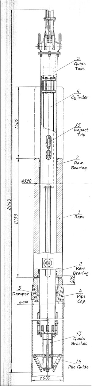
The hydraulic hammer (Figures 1-10,12-13, see below) consists of the following components:
- Ram 42 in the shape of a massive, thick walled cylindrical pipe with two circular sliders 84;
- Tubular casing 30 which is used as a central guide along which ram 42 moves;
- Pile cap 24 inside which damper 36 is located to decrease dynamic efforts acting on casing while pile driving;
- Hydraulic cylinder 96 with the system of control valves and accumulators that are located inside casing 30 of the hammer;
- Traverse 88 attached to the rod ear of the cylinder 96. The ends of traverse 88 are passing through longitudinal slots in walls of casing 30 and are attached to the ram 42 via dampening blocks 84;
- Upper cap 66, which is attached to the casing 30 and cylinder 96 via a flange. There are guides provided to support the high-pressure hoses. There are provided ears 64 to hang hydraulic hammer to the hook of the crane;
- At the bottom of the hammer there is a system of adjustable mechanical supports 58 to prevent hammer from rollover while driving of batter (inclined) piles.The hydraulic operating and control system (Figure 11) likewise is made up of the following:
- Power pack comprising two parallel 3-plunger pumps 128 equipped with electric drive and thyristor control, coarse filters 126 and fine filters 132, safety valves 136 (which are included into pumps 128), back valve 130, valve unit 138, manometer 140 and drain valve unit 142;
- Working cylinder 96 with rod 102 and control cylinder 188, the upper part of which is fixed to the working cylinder 96;
- High-pressure hose 110 to supply working fluid from the power pack to the cylinder;
- Hydro-pneumatic accumulator 116 to smooth pressure fluctuations in the pressure line.
The control system (Figure 11) is constituted as follows:
- Two-position main valve 180 with large nominal bores which provides either connection piston end or rod end of the cylinder motor or disconnection of these ends and connection piston end with drain line;
- Two-position control valve (“pilot”) 176 with small nominal bores which controls main valve 180’s position;
- Ram height adjuster made in the shape of a plunger 210 attached by its bottom end to the rod 94 and passing into the internal slot of control cylinder 188;
- Hydro-pneumatic accumulator 120, which is connected via pipe lines with internal cavity of control cylinder 188 and via back valve 204 with pressure line of the power pack;
- Mechanism of impact energy adjustment comprising of the adjustable reduction valve 146, valve unit 144, hydro-pneumatic accumulator 118 and manometer 148;
- Differential hydraulic block 192 of pressure comparing in which values of fluid pressure from ram height adjuster and reduction valve 146 are compared. Block 192 is designed in the shape of piston-valve with a pusher. The area of the piston from the side of hydro-pneumatic accumulator 120 is half of the piston area on the side of hydro-pneumatic accumulator 118.
Hydraulic system of hammer starting and stop (Figure 11):
- Sliding valve 156, which is driven from mechanical device providing its switching directly after ram 42 impact upon the pile cap, valve unit 150, adjustable valve 152 and hydromechanical pusher 175 which controls pilot valve 176 position.
- Two (2) small flexible high-pressure hoses 112 and 114 supply working fluid into the control system of the hammer. Hydraulic system of control provides to perform from the control panel, located at the base platform, hammer starting, impact energy adjustment, stop of the hammer and making single blows of the predetermined impact energy.
Operation
The control system is free of electrical or electronic control. To accomplish this there is a centre bore in the cylinder’s piston rod. A tube extends from the top of the cylinder which fits into this bore; in turn a rod from the bottom of the main piston rod fits into the centre bore of the tube. The accumulator connected direct to the control valve has its pressure set to a desired level before the hammer’s operation starts. As the ram rises, the fluid above the central rod and inside the tube is forced upward into the accumulator. When the accumulator’s pressure (and thus the pressure of this control fluid) is sufficiently high, the hydraulically operated control/pilot valve is shifted, which in turn shifts the main valve.
Opposing this motion is the pressure on the other side of the pilot cylinder; as this pressure is varied, the point in the stroke at which the valve shifts is likewise varied. This opposing pressure is controlled by the needle valves on the power pack.
To shift the valve back at the bottom of the stroke, a roller-actuated valve is mounted so that the ram releases it near impact. This admits pressure on the other side of the control valve and shifts the valve back to depressurizing the topside of the piston. It is noteworthy that the lower side of the piston is always pressurized and pressure is alternately applied to the upper side of the piston. This helps even out the flow and also always provides for some kind of downward assist.
Prototype Unit
Vulcan commissioned a set of drawing for a prototype unit. Specifications for it are shown below. The actual production hammers could of course range in sizes comparable to hydraulic hammers suitable for the large offshore pipe piling.
SI Units English Units Rated Striking Energy, kJ 50 Rated Striking Energy, ft-lbs 23813 Ram Mass, kg 3000 Ram Weight, lbs. 6615 Stroke, mm 1500 Stroke, inches 38.10 Energy with Free Drop, kJ 44.1 Energy with Free Drop, ft-lbs 21003 Percentage of Energy w/Free Drop 88% Percentage of Energy w/Free Drop 88% Blows Per Minute 25 Blows Per Minute 25 Power Output, kW 20.8 Power Output, HP 28 Hydraulic Flow, l/min 132 Hydraulic Flow, gpm 35 Maximum Pressure, MPa 20 Maximum Pressure, psi 2901 Hydraulic Power Input, kW 44 Hydraulic Power Input, HP 59 Percentage of Hyd. Energy over Theoretical Minimum 211% Percentage of Hyd. Energy over Theoretical Minimum 211% 


Drawing Nomenclature
- 20 pile hammer
- 21 lower end portion
- 22 hollow piling
- 24 annular pile cap
- 25 inwardly directed lower end flange
- 26 recess or shoulder
- 27 central body recess
- 28 bore
- 30 elongated, upstanding, hollow tubular base
- 32 annular, circular support ring
- 34 radial pins
- 36 shock absorbent material
- 38 upper end portion
- 40 annular, upper end face or anvil surface
- 42 hollow, heavy, generally cylindrically shaped ram
- 44 annular lower end surface
- 45 finger
- 46 plurality of radially oriented, upwardly and outwardly sloping vent passages
- 48 plurality of openings
- 50 lower end wall
- 52 large central part
- 54 guide assembly
- 56 radially extending fingers
- 58 enlarged head
- 60 bracket or block
- 62 lift ring assembly
- 63 pins
- 64 apertured lift eye
- 66 top plate
- 68 central bore
- 70 matching size, upper end face
- 72 upper annular groove
- 74 lower annular groove
- 76 upper resilient shock ring
- 78 lower resilient shock ring
- 80 wall ports
- 82 diametrically opposed, radially oriented bores
- 84 annular, resilient, shock element bearings
- 86 opposite, axle ends
- 88 transverse lift yoke
- 90 longitudinally extending diametrically opposite guide slots
- 92 clevis
- 94 piston rod
- 96 fluid operated lift cylinder
- 98 removable cross pin
- 100 annular lower end wall
- 102 piston
- 104 upper end wall
- 106 hydraulic base element
- 108 power pack
- 110 large diameter, flexible, pressure line
- 112 regulating control line
- 114 small bore flexible line
- 116 crank end hydraulic accumulator
- 118 head end accumulator
- 120 control accumulator
- 122 fluid supply reservoir
- 124 check valve
- 126 filter
- 128 hydraulic pump
- 130 filter check valve
- 132 pump filter
- 134 high pressure manifold
- 136 adjustable relief valve
- 138 manual dump valve
- 140 main pressure gauge
- 142 depressurizing manual dump valve
- 144 manual, two-way control valve
- 146 manually adjustable pressure reducing valve
- 148 control line pressure gauge
- 150 manual operation valve
- 152 pressure relief valve
- 154 passage or line
- 156 mechanically controlled valve
- 158 mechanism
- 160 cam follower roll
- 162 axle
- 164 pivot arms
- 166 spaced apart brackets
- 167 spring
- 168 stem
- 170 slot
- 172 cam
- 174 line
- 175 pusher
- 178 comparator valve
- 180 main operating valve
- 182 head end main operating valve connecting line
- 184 crank end main operating valve connecting line
- 186 crank end manifold
- 188 small diameter inner control cylinder
- 190 small diameter inner control cylinder line
- 192 differential pressure block
- 194 upper pusher
- 196 main pilot valve
- 198 top pilot line
- 200 bottom pilot line
- 202 interconnection line
- 204 interconnection check valve
- 206 piston check valve
- 208 inner cylinder lower end portion
- 210 control rod
- 214 head end accumulator line
- 215 alternate guide system
- 216 heavy counterweight
- 218 elongated hollow tubular outer shell
- 220 upper annular end wall
- 222 lower annular end wall
- 224 hollow tubular ballast element
- 226 elongated tubular inner side wall
- 228 support ring
- 230 second alternate guide system
- 232 relatively light weight and short length tubular outside side wall
- 234 annular, radial end wall
- 236 plurality of ports
- 238 inner side wall
- 240 radial support pins


11 thoughts on “Sea Water Pile Hammer”