
Vulcan hammers were justifiably admired for their simplicity. However, many of the keys to success were in two fields:
- their design and construction, and;
- how the hammer was equipped with its accessories.
Here we feature a few of both; one or more of them may appear on or with your Vulcan hammer. For more practical “tips” on how to maintain your Vulcan hammer, click here.

The point is raised and carefully aligned to the ram point hole. The clearance between the heated ram and the point is generally only a few thousanths of an inch, so alignment is critical. The ram point is then lowered until it seats against the bearing surface. On top of his work is Vulcan field service representative Norris Tremmier. Photos courtesy of Jonathan Tremmier/Pile Hammer Equipment.

The prime mover for the system, in this case a Johnston boiler. Steam was the original method for powering Vulcan hammers, but the maintenance hastened the switch to air for onshore hammers. For offshore hammers, though, steam remained the motive fluid of choice for many years. Although onshore contractors generally used upright, water-tube boilers (Raymond was the best example of this,) the Scotch marine, fire-tube type is really better, as it has more reserve of steam to handle the intermittent flow requirements of the hammer. Vulcan’s customers generally purchased their own boilers, but every now and then Vulcan would sell a “package deal” to an end user. This was the case in Vulcan’s first sale to the People’s Republic of China. Ten years later they would do the same thing with the Korean contractor Daelim, and their new Johnston boiler is shown here.

A close-up of suspension cables, which became the accepted method of suspending Vulcan offshore hammers from the offshore type leaders. Onshore hammers used sheaves to raise and lower the hammer, but this was not applicable to a stub leader. Originally Vulcan intended for its customers to use the bar head (the bar is at the centre of the hammer on the 560 hammer on the left, between the two spelter sockets) and use a clip-secured wrap between the leader and the hammer. The suspension cables, attached in pairs to both hammer and leaders, proved a cleaner and more reliable method of doing this. In these photos spelter sockets are shown, but Vulcan furnished (when the customer needed them) swaged sockets. In either case the hammer was given sufficient leeway to ride down with the pile it was driving and give the crane operator the opportunity to keep the leader moving with the hammer without the cables becoming tight.

An overview of suspension cables, which became the accepted method of suspending Vulcan offshore hammers from the offshore type leaders. Onshore hammers used sheaves to raise and lower the hammer, but this was not applicable to a stub leader. Originally Vulcan intended for its customers to use the bar head (the bar is at the centre of the hammer on the 560 hammer on the left, between the two spelter sockets) and use a clip-secured wrap between the leader and the hammer. The suspension cables, attached in pairs to both hammer and leaders, proved a cleaner and more reliable method of doing this. In these photos spelter sockets are shown, but Vulcan furnished (when the customer needed them) swaged sockets. In either case the hammer was given sufficient leeway to ride down with the pile it was driving and give the crane operator the opportunity to keep the leader moving with the hammer without the cables becoming tight.

The Manzel type of lubricator, more common with the offshore hammers. This lubricator was a series of injectors (similar to fuel injectors on an automobile or truck) which were driven by a small electric motor. A steady stream of lubricant is injected into the line. Use of proper air or steam lubricant insures that the oil emulsifies with the flow and spreads throughout the cylinder and valving.

The Vulcan Sight Feed Line Oiler, which uses an injection similar to a carburettor. This is similar in concept to the McCall Lubricator featured on many Raymond rigs. The lubricant tank is integral to the unit, below the air/steam inlet/outlet. Simple in concept and operation, it made it easy to keep the cylinder lubricated. This oiler is lubricating Vulcan’s experimental Single/Compound hammer; usually the oilers were mounted on the air compressor or near the boiler in a more permanent fashion.

The “outside” of the Hydra-Nut (U.S. Patent 3,938,427.) Introduced in the 1970’s to directly replace the cable nuts (as shown above,) the Hydra-Nut simplified the process of tensioning the cables. The Hydra-Nut was screwed on without the cast thread protector cap on the top, the cable was lightly tensioned with a “manual jack,” the threaded sleeve was screwed down on the cable fitting and tightened against the jack body, the manual jack removed and thread protector cap replaced (aligning the flats on the cable fitting with those on the cap,) then the chamber was pressurised through the grease fittings to the pressure where the cables would have their proper, full tension. The weakness of the Hydra-Nut was in the grease fittings; should dirt or paint get in them, the chamber would depressurise and the cables would be loose. This was more probable when 1/8″ Zerck fittings were used than with the button head fittings as shown. Vulcan addressed this issue in the 1980’s with the Auto-Jack, which altered the Hydra-Nut by adding an internal cable nut with the integral jacking cylinder, which was then depressurised when the cable achieved proper tension.

Details and instructions for a jacking pedestal.

The “inside” of the Hydra-Nut (U.S. Patent 3,938,427.) Introduced in the 1970’s to directly replace the cable nuts (as shown above,) the Hydra-Nut simplified the process of tensioning the cables. The Hydra-Nut was screwed on without the cast thread protector cap on the top, the cable was lightly tensioned with a “manual jack,” the threaded sleeve was screwed down on the cable fitting and tightened against the jack body, the manual jack removed and thread protector cap replaced (aligning the flats on the cable fitting with those on the cap,) then the chamber was pressurised through the grease fittings to the pressure where the cables would have their proper, full tension. The weakness of the Hydra-Nut was in the grease fittings; should dirt or paint get in them, the chamber would depressurise and the cables would be loose. This was more probable when 1/8″ Zerck fittings were used than with the button head fittings as shown. Vulcan addressed this issue in the 1980’s with the Auto-Jack, which altered the Hydra-Nut by adding an internal cable nut with the integral jacking cylinder, which was then depressurised when the cable achieved proper tension.

A photographic “exploded view” of the Vari-Cycle. It uses the “old” Vulcan part numbering system, which was used until the early 1970’s. Many parts still get ordered using that system.

The Vulcan Vari-Cycle, again for the 020 offshore hammer. This works by shifting the movable trip (the trip with the arc slot) between two different cut-off wedges, which in turn varies the stroke. Variable stroke is essential for concrete piles to control tensile stresses. For offshore hammers, it is not so critical, which led to the use of “manual” overrides such as the traverse trip. This also shows the outboard bearing bracket, which is necessary for virtually any trip shifting device.

A Vulcan 030 offshore hammer, ready for shipment. This hammer sports what is probably the best ram key retaining system Vulcan used, i.e., the set screws visible under the ram keys. Also visible is the Vari-Cycle out front of the steam chest on the cylinder. Generally, Vulcan mounted the Vari-Cycle so that the cylinder would sit flat on top of the steam chest, but in the case of these hammers it was placed at an angle. Also note that the ram is blocked in the middle of the columns, between the cylinder and the base. In the late 1970’s Vulcan changed this procedure so that the ram was pushed to touch the base and blocked. Although it moved the centre of gravity of the hammer towards the base, it also enabled the hammer to be set upright without having to block the ram first.

A Vulcan 060 hammer sporting ram key wedges and ram key wedge bolts. Keeping ram (and column) keys tight is principally a matter of three things: Having straight keys. Having key slots in good condition. Proper tightening, not too much and not too little. Any retainers used are a supplement. Although the ram key wedges were used on the Vulcan 060, 560, 3100 and 5100 hammers, they were not the optimal method of ram key retention.

Ram point installation by cooling the point. Breakage of ram points is a major repair job in a Vulcan hammer (caused, in some cases, by use of wire rope biscuit as you see above.) Getting the “stump” of the point out was half the battle; click here for Vulcan’s recommendations. Putting one in was the other (also important for new rams and points.) For the smaller hammers, a press would do, but for hammers such as the Vulcan 5110, the best way was to shrink the point through freezing the small end (the “stump” when broken,) lifting it up and lowering it into a ram turned upside down. Although Vulcan installed points in new and used rams using this procedure, this is a very delicate procedure, failure of which could result in a cracked ram, point, or having the point hung up in the ram, which ruins both. As they say, “don’t try this at home!”

Wire rope biscuits. Vulcan hammers were originally designed for hardwood cushions such as oak, a commodity that became rarer as the years went by. This led to a great deal of experimentation on the part of contractors for suitable cushion materials, which were necessary to reduce both hammer and pile stresses. One of the more popular expedients was the wire rope biscuit. As shown, it involved using cable (frequently used cable from the crane or heavy lift rigging) coiled up and tack welded. These “biscuits” were then alternated with steel plates in the cushion stack. This provided the contractor with a cheap, plentiful supply of cushion material, especially offshore. It was necessary, however, for the contractor to change the biscuits frequently, as wire rope turned into a solid steel mass with extended driving. The failure of many contractors to do this could lead to hammer damage; this led the factory to become progressively more cautious in recommending its use. Most offshore contractors came to furnish the barge with more than one pipe cap per hammer. This enabled the user to switch pipe caps (and thus cushion pots) and repack one pipe cap while driving with another. This also encouraged more frequent changes in cushion material.

This ram point insertion was done 28 September 1979 at Smith Harris machine in Cleveland, OH. It was a replacement point for a Vulcan 5100, S/N GH-1030. The original ram point was inserted after the ram was heated in a foundry heat treating furnace. Unfortunately, the foundry let the ram cool too quickly in the cool New England fall, and the ram cracked at the corner of the ram point hole. Attempts to metal stitch the ram back together lasted only a few minutes in offshore service, thus the replacement of the ram and point. As we say, don’t try this at home! Returning to our procedure, after this, the point is brought down, as shown to the right.

Although Vulcan’s cushion system came in for criticism by some operators (especially Heerema) for being too soft, in operation it was surely superior to Menck’s, with its “Parquet floor” of azobe/bongossi hardwood, which burnt magnificent tropical hardwood in less than 3000 blows. An example of this kind of cushion configuration is shown below, stacked up in McDermott’s Amelia yard in February 1994.

Hammer cables being tightened on a Vulcan 020 hammer. Vulcan was relatively slow (compared to Raymond, for example) in adapting cable ties to keep its hammers together. The demands of offshore pile driving forced Vulcan to make this change. Offshore hammers generally used cast spelter fittings with an anti-rotational tab on the lower fitting as well as the flats on the upper one. A jacking pedestal is first set over the cable and loose nut; then a jacking bar is threaded over the cable fitting and slid through a centre hole jack. The jack is then pressurised and, when the proper tension is achieved, the cable nut is tightened and the tension from the jack released. Offshore crews (especially in the Gulf) disliked this procedure, which led to the development of internal jacks such as the Hydra-Nut (shown below) and Auto-Jack. This procedure, however, is still the preferred way to tighten single-acting onshore hammer cables, providing (as always) the proper safety precautions are taken.

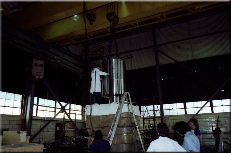
Ram point installation by heating the ram. Although it’s intuitive that, since the ram point is lighter, it’s easier to cool the point, heating the point can be advantageous because it’s simpler to keep the ram hot until the point is inserted, as opposed to the cold point, which is warming up from the second it’s removed from the cold liquid nitrogen. First, the ram is brought up to proper expansion temperature using electric resistance heaters and insulating blankets, to properly control heating and cooling, as shown below.

The first step is to build an insulated box with a hole in the centre and surround the hold with liquid nitrogen (shown below, with the large diameter of the point sticking out of the top.) When cooled enough, the point is then taken out and very slowly lowered into the ram (as shown to the left,) making sure it is straight.

The point is raised and carefully aligned to the ram point hole. The clearance between the heated ram and the point is generally only a few thousanths of an inch, so alignment is critical. The ram point is then lowered until it seats against the bearing surface. On top of his work is Vulcan field service representative Norris Tremmier. Photos courtesy of Jonathan Tremmier/Pile Hammer Equipment.


5 thoughts on “It’s in the Details”