
When installing a Piston and Rod in certain Vulcan Offshore Pile Hammers, it is necessary to take certain precautions to assure that all parts are properly assembled one with another and that subsequent to assembly proper working clearances exist. This particular instruction sheet refers to the installation on the following sizes of Hammer:
010 – 014 – 016 – 020 – 030 – 340 – 360 – 540 – 560 – 3100 – 5100 – 140C – 200C – 400C
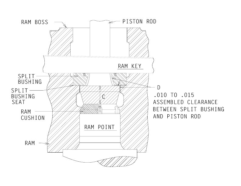
Prior to reassembling the Ram Keys to attach the lower end of the Piston Rod to the Ram, it is necessary to accurately determine the distance between the Split Bushing Seat, Letter A, and the top of the Ram Cushion, Letter B. The most accurate means of determining these two dimensions, as well as the difference between them, is as follows:
- Using the boss on top of the Ram as a reference point, place a precision ground bar across the center hole of the Ram.
- Using a depth micrometer, measure the distance from the underside of the precision ground bar to the Split Bushing Seat, Letter A.
- Then measure the distance from the underside of the Precision Ground Bar to the top surface of the Ram Cushion, Letter B.
- The difference between these two dimensions is the distance between the Split Bushing seat and the top of the Ram Cushion. This distance should be .010″ to .015″ greater than the thickness of the flange at the lower end of the Piston Rod indicated by Letter C.
- If it is necessary to increase this distance, or measurement, remove the Ram Cushion from the Ram and reduce its thickness by lathe turning to the required dimension.
- If it is necessary to diminish this distance, or measurement, place a steel shim of correct thickness underneath the Ram Cushion on the top surface of the Ram Point.
- When the Ram Keys are driven securely into place, the Split Bushing will be clamped tightly against its Seat inside the Ram.
- With the Split Bushing thoroughly clamped in place against its seat, the Piston Rod must be free to move laterally. This lateral movement is allowed by the clearances provided by this installation method. Lateral movement clearances are allowed for at points indicated by Letter D.
Note: This procedure is also good for the Vulcan 18C, 30C, 50C, 65C, 80C, 85C, 100C, 520, 530, 535, 5110, 5150 and 6300 hammers. The tip was intended for offshore hammers, but it is also good for onshore hammers of these sizes. The ram key arrangement for smaller hammers is shown in Onshore Tip 18.


5 thoughts on “Vulcan Offshore Tips #15: Piston and Rod Installation”