
First, we need to review what we’ve learned from our previous posts on diesel hammers. First, the posts themselves:
- Diesel Hammers: Rated Striking Energy, and Should Diesel Hammers Be Derated?
- Diesel Hammers: Delmag, Nilens and the Method of Analysis
- Diesel Hammers: The Russian Hammers and Hemi-Headed Pile Drivers
- Diesel Hammers: Pileco
Now we can discuss what we have learned from this analysis:
- The “catch ring stroke” has been on a general upward trend. We can see this from the Delmag D22 (2521 mm) to the Pileco D25-22 (4176 mm.)
- Likewise the thermodynamic energy–and its portion of the “catch ring energy” have increased as well.
- The measured maximum combustion pressures as represented in the database have increased, although the compression ratios have not increased.
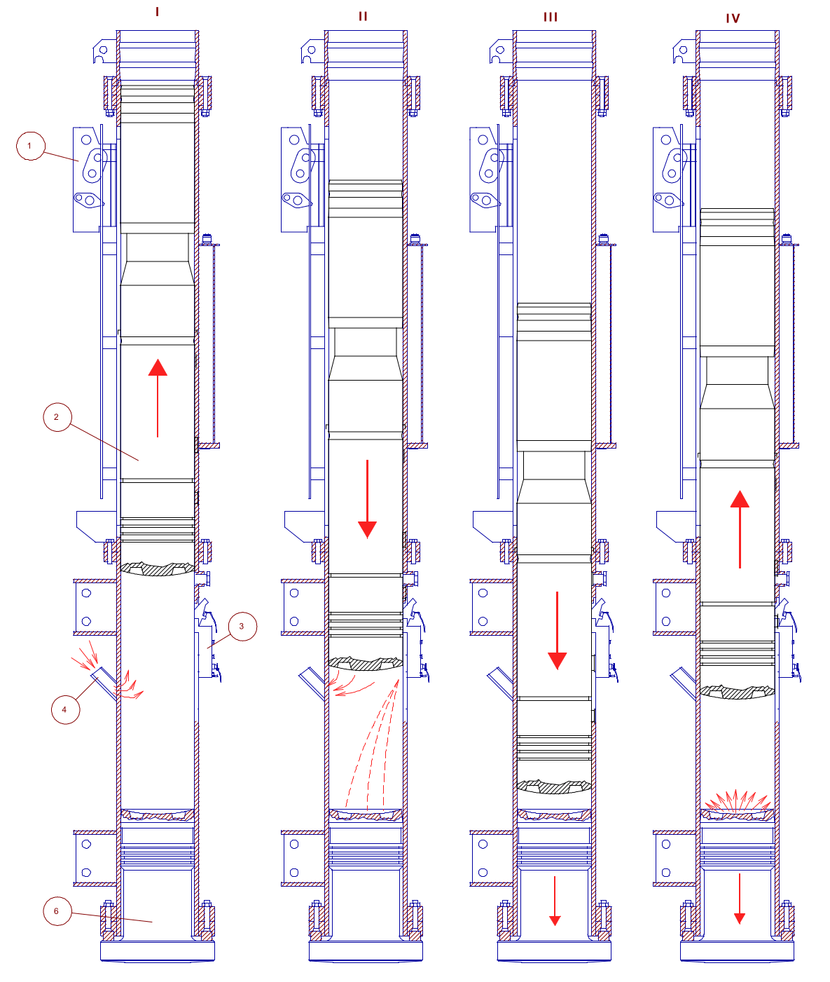
- None of the diesel hammers–past or present–can produce the thermodynamic energy necessary to achieve the catch ring stroke. The only way this will take place is if we have rebound or some excessive combustion from a source other than the fuel pump (like this.) It is in reality undesirable for them to do so. It is more difficult to regulate the stroke in a diesel hammer than, say, an external combustion hammer, because of the complex interaction between the ram, the combustion process, the anvil and the pile-soil system; it is the price one pays for the convenience of not having an external power source. In any case when rebound becomes a significant part of the stroke it is because energy being put into the pile-soil system is coming back into the hammer, and thus there is a great deal of energy that is being traded between the ram and the rest of the system. Such energy is not going into pile penetration, which is not good practice either from an equipment standpoint or from a job progress standpoint.
The Vulcan “Series II” Pile Hammers
With its unhappy experience with the diesel hammers it developed in the 1980’s, Vulcan’s objective was to develop a diesel hammer with the following characteristics:
- It wanted a design that was robust, reliable and simple.
- It wanted a design which accommodated U-type leaders.
- It wanted a design that was free of castings. Castings had been Vulcan’s main purchasing challenge–one that came to affect its relations with its customer base–especially during the offshore boom years of the 1970’s and 1980’s. The American foundry system had been in decline throughout that period, a decline that has not stopped to this day. It is difficult to envision building a pile hammer in the U.S. today with the foundry system we have to work with.
- It wanted a hammer with a catch ring stroke that was more comparable with those of Delmag and its Chinese progeny, something that, as we have seen, was on the increase.
- It wanted a design that could be either produced at the Chattanooga facility or one that could be outsourced in other places. The fabricating capabilities of that facility had improved tremendously during the early 1990’s, which made getting away from cast components for a product such as this a possibility. The machining and assembly of such a hammer were well within its capabilities. One option for overseas production was obviously Russia, but the difficulties experienced with the “Series I” made Vulcan management very aware of the difficulties of this option, and in any case Vulcan wasn’t much on outsourcing either its components or products outside of the U.S..
- It wanted a design that it could easily modify if the conditions warranted a modification.
Many within the company did not appreciate the thought process behind commissioning the design of the Series II hammers, let along bringing the Series I into the country.
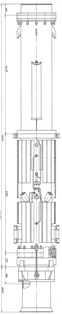
In any case the specifications for the Series II is given below.
| Russian Designation | SO-310 | SO-311 | SO-312 | SO-313 | SO-314 | SO-315 |
| Vulcan Designation | V13 | V19 | V25 | V35 | V50 | V75 |
| SI UNITS | ||||||
| Rated Striking Energy, kJ | 36.8 | 55.9 | 73.5 | 102.9 | 147.0 | 220.5 |
| Minimum Hammer Energy, kJ | 18.4 | 27.9 | 36.8 | 51.5 | 73.5 | 110.3 |
| Mass of Ram, kg | 1,250 | 1,900 | 2,500 | 3,500 | 5,000 | 7,500 |
| Maximum Ram Stroke, mm | 3,000 | 3,000 | 3,000 | 3,000 | 3,000 | 3,000 |
| Number of Blows Per Minute of Ram @ Maximum Stroke | 42 | 42 | 42 | 42 | 42 | 42 |
| Fuel Capacity, l | 12 | 24 | 38 | 78 | 53 | 138 |
| Mean Fuel Consumption, l/hr | 12 | 13 | 12 | 16 | 24 | 35 |
| Mean Oil Consumption, l/hr | 0.3 | 0.3 | 0.3 | 0.4 | 0.5 | 0.5 |
| Maximum Pile Batter | 1:3 | 1:3 | 1:3 | 1:3 | 1:3 | 1:3 |
| Total Hammer Mass (including crab), kg | 2,750 | 3,900 | 5,480 | 7,720 | 9,400 | 16,590 |
| Distance Between Jaws, mm | 508 | 660 | 660 | 813 | 813 | 940 |
| Width of Jaws, mm | 210 | 235 | 235 | 286 | 286 | 286 |
| Length, mm | 635 | 775 | 815 | 865 | 865 | 1,080 |
| Width, mm | 700 | 725 | 800 | 953 | 953 | 1,100 |
| Height, mm | 4,400 | 4,400 | 4,980 | 6,360 | 5,360 | 5,840 |
| ENGLISH UNITS | ||||||
| Rated Striking Energy, ft-lbs | 27,128 | 41,235 | 54,257 | 75,960 | 108,514 | 162,771 |
| Minimum Hammer Energy, ft-lbs | 13,564 | 20,618 | 27,128 | 37,980 | 54,257 | 81,385 |
| Weight of Ram, lbs. | 2,756 | 4,190 | 5,513 | 7,718 | 11,025 | 16,538 |
| Maximum Ram Stroke, in. | 118 | 118 | 118 | 118 | 118 | 118 |
| Number of Blows Per Minute of Ram @ Maximum Stroke | 42 | 42 | 42 | 42 | 42 | 42 |
| Fuel Capacity (with standard tanks), gal | 3 | 6 | 10 | 20 | 14 | 36 |
| Mean Fuel Consumption, gal/hr | 3 | 3 | 3 | 4 | 6 | 9 |
| Mean Oil Consumption, qt/hr | 0.3 | 0.3 | 0.3 | 0.4 | 0.5 | 0.5 |
| Maximum Pile Batter | 1:3 | 1:3 | 1:3 | 1:3 | 1:3 | 1:3 |
| Total Hammer Weight (including crab), lbs. | 6,064 | 8,600 | 12,083 | 17,023 | 20,727 | 36,581 |
| Distance Between Jaws, in. | 26 | 26 | 26 | 26 | 26 | 26 |
| Width of Jaws, in. | 9.25 | 9.25 | 9.25 | 9.25 | 9.25 | 9.25 |
| Length, in. | 25 | 31 | 32 | 34 | 34 | 43 |
| Width, in. | 28 | 29 | 31 | 38 | 38 | 43 |
| Height, in. | 173 | 173 | 196 | 250 | 211 | 230 |
So how would these hammers perform using our analysis? They’re based on the hammers featured in Diesel Hammers: The Russian Hammers and Hemi-Headed Pile Drivers which are, as you can see, variable in their results. One modification possible is to change only two parameters: the combustion chamber volume and the working stroke of the hammer. (They, in turn, affect other parameters as well.) The results of those modifications (which are noted in bold print) are shown below.
| Model | SO-310 | SO-311 | SO-312 | SO-313 | SO-314 | SO-315 |
| Ram mass, kg | 1250.0 | 1900.0 | 2500 | 3500 | 5000 | 7500 |
| Compression volume, mm3 | 1784588 | 3079317 | 4463529 | 6034816 | 7668183 | 11602960 |
| Ratio of compression volume to ram mass, mm3/kg | 1427.7 | 1620.7 | 1785.4 | 1724.2 | 1533.6 | 1547.1 |
| Cylinder diameter, mm | 300 | 345 | 400 | 470 | 470 | 660 |
| Cylinder cross-sectional area, mm2 | 70686 | 93482 | 125664 | 173494 | 173494 | 342119 |
| Probable working stroke from drawings or adjusted working stroke, mm | 325 | 425 | 425 | 425 | 550 | 425 |
| Actual expansion volume, mm3 | 24757484 | 42809174 | 57870604 | 79769959 | 103090132 | 157003722 |
| Ratio of Free Air Volume to ram mass, mm3/kg | 19806 | 22531 | 23148 | 22791 | 20618 | 20934 |
| Actual compression ratio | 13.9 | 13.9 | 13.0 | 13.2 | 13.4 | 13.5 |
| Maximum Physical Stroke, m | 3.416 | 3.390 | 3.613 | 3.810 | 3.810 | 3.675 |
| Maximum Energy from Maximum Physical Stroke, kJ | 41.9 | 63.2 | 88.6 | 130.8 | 186.9 | 270.4 |
| Actual Working Volume, m3 | 0.0230 | 0.0397 | 0.0534 | 0.0737 | 0.0954 | 0.1454 |
| Ratio of actual working stroke to cylinder diameter) | 1.08 | 1.23 | 1.06 | 0.90 | 1.17 | 0.64 |
| Initial Pressure (p1), MPa | 0.115 | 0.115 | 0.115 | 0.115 | 0.115 | 0.115 |
| Gas Constant k | 1.25 | 1.25 | 1.25 | 1.25 | 1.25 | 1.25 |
| Compression Pressure (p2), MPa | 3.079 | 3.087 | 2.829 | 2.898 | 2.960 | 2.985 |
| Maximum Combustion Pressure (p3), MPa | 10.00 | 10.00 | 10.00 | 10.00 | 10.00 | 10.00 |
| Ratio of Combustion Pressure to Compression Pressure | 3.25 | 3.24 | 3.53 | 3.45 | 3.38 | 3.35 |
| Total Thermodynamic Energy, kJ | 23.805 | 41.052 | 60.558 | 81.521 | 103.160 | 155.835 |
| Ratio of Thermodynamic Energy to Maximum Stroke Energy | 56.83% | 64.97% | 68.34% | 62.32% | 55.20% | 57.63% |
| Mean Effective Pressure from Energy and Actual Working Volume, kPa | 1036.241 | 1033.267 | 1133.890 | 1105.595 | 1081.090 | 1071.764 |
The results show parameters such as the compression ratio, the ratio of thermodynamic energy to maximum stroke energy and the mean effective pressure to be in line with newer hammers. All of the working strokes were changed; the only compression volume that was not changed was the SO-315, ironically the only one with a true toroidal combustion chamber. These changed parameters do not consider the secondary geometric effects of their change such as the position of the fuel pump.

