

With recent upheaval over tariffs and our long-term commercial relationship with China, one is led to wonder: is the era of the “Chimags” at an end? Or at least not what it used to be? And could another different diesel hammer be manufactured in the U.S. (yes, there are other manufacturers)?
In this series we’ll look at these questions through the lens of two of Vulcan’s efforts to produce a diesel hammer: Nilens and the relationship with the Russians in the 1990’s. We’ll certainly bring in other diesel hammers for comparison and in the process try to shed some light on a topic that has been obscured by years of inadequately substantiated claims.
Some Basic Thermodynamics
In the post Some Insight into the Origin of Vulcan’s Pile Hammer Valve System we saw the way in which steam engines inspired/informed the design of the classic Warrington-Vulcan pile hammer. Diesel engines–those venerable prime movers of virtually every external combustion hammer–were likewise the starting point of the diesel hammer, developed in Germany between the two World Wars. The difference is that there is much more interaction between the diesel combustion and energy process in a diesel hammer and the impact of the ram with the pile than with externally pressurised fluids such as air, steam or hydraulic fluid. This complexity has made both development and application of diesel hammers more involved than other types.
Although we call these diesel hammers, and that’s certainly the case because of a) they are compression ignition engines and b) use diesel fuel, the thermodynamic cycle is in reality an Otto Cycle. (The familiar diesel hammer cycle can be found in both the Nilens and Russian Diesel Hammers posts.) This is illustrated in a figure from this document, produced in the early years of the development of the wave equation program:
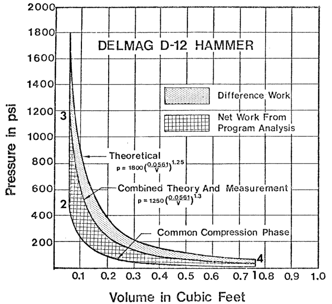
There are four parts to this cycle:
- 1-2 Compression from atmospheric (or nearly so) pressure to the maximum pressure before combustion, assumed an isentropic/adiabatic process
- 2-3 Combustion in the combustion chamber after (hopefully) the addition of fuel, assumed a constant volume process
- 3-4 Expansion of the burnt fuel-air mixture, again assumed an isentropic/adiabatic process
- 4-1 Exhaust, assumed for thermodynamic purposes to be a constant volume process
Let us make a few assumptions and definitions:


The area defined by the hatched area in the above figure is the work/energy obtained for each hammer cycle. (This is referred to as the indicated area, and this is explained for air/steam hammers in the post Indicator Devices and Cards for Vulcan Hammers.) From Faires and Simmang (1978), that area/work is

Making substitutions from Equations (1-5) yields

We put it in this form because we want to concentrate on the important parameters:
atmospheric pressure (or close to it)
maximum combustion pressure
compression ratio, see Equation (3)
ideal gas constant, see Equation (4)
compression volume, see Equation (1)
Equation (7) is crucial because it represents the entire energy that is put into the system by the hammer. There is no other, something that is important when we consider the rating of diesel hammers.
Mean Effective Pressure
We see from the figure above that the pressure on the ram (and the anvil) vary continuously and significantly with compression, combustion and expansion. Air and steam hammers, for example, which do not use the motive fluid expansively have, in theory at least, a constant pressure on the piston. What would be the pressure for the same work or energy if it were uniform over the distance the pressure acts?
Let us begin by defining the working volume of the diesel hammer as

The working stroke (the distance between impact and the point where the piston closes or opens the combustion region to the atmosphere) is thus

where 
The mean effective pressure is thus defined as

and

and combining this with Equations (6) and (7) yields

Since we said that the entire energy of the hammer comes from the thermodynamic cycle, if we ignore friction we can (from Diesel Hammers) estimate the impact velocity by solving the equation

to

In these equations 

The significance of all of this will become more evident as we move forward.
References (other than those hyperlinked):
Faires, V.M. and Simmang, C.M. (1978) Thermodynamics. Sixth Edition. New York: Macmillan Publishing Co.


3 thoughts on “Diesel Hammers: Some Basic Thermodynamics, and the Mean Effective Pressure”