
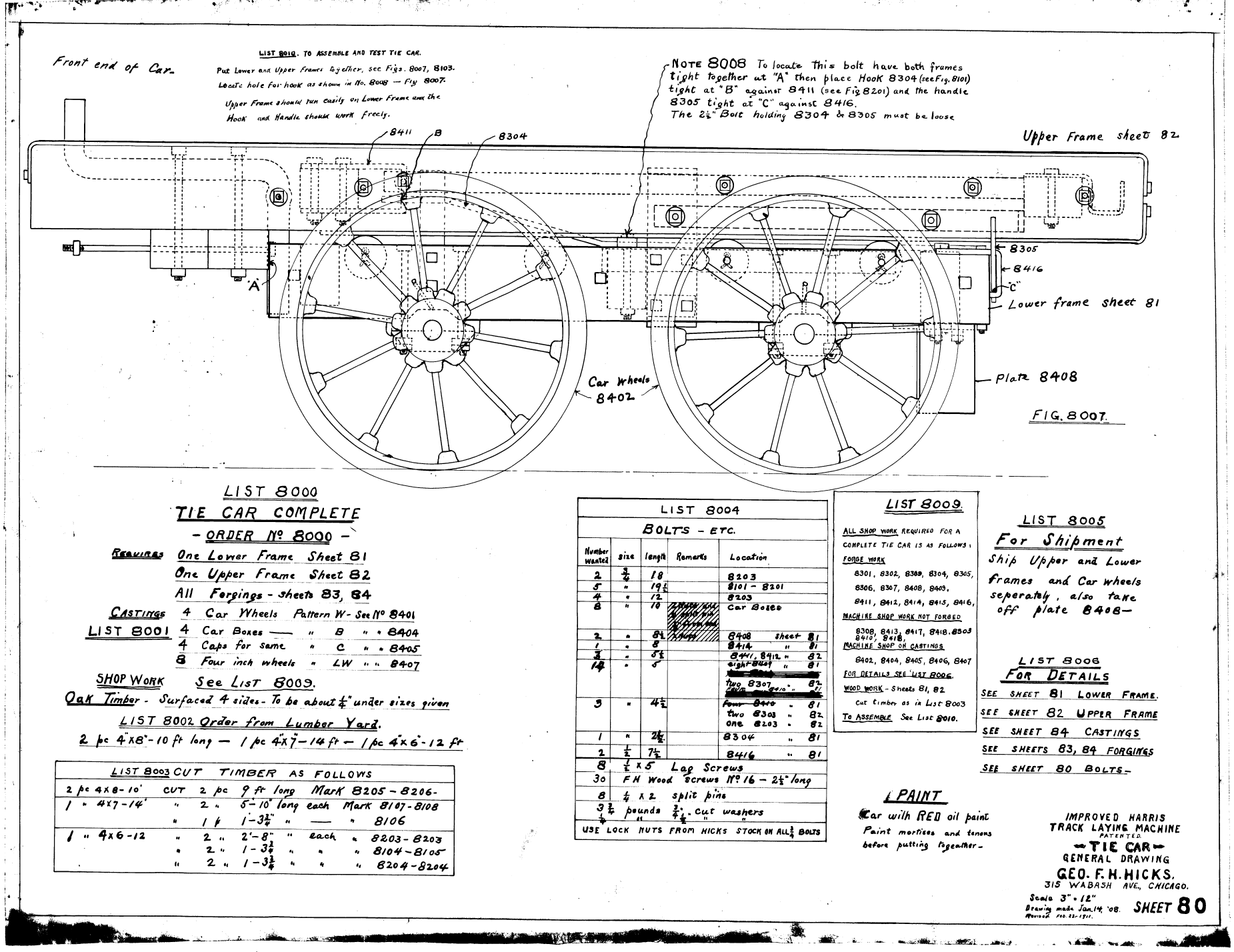
As noted elsewhere, Vulcan got itself into many products outside of pile driving equipment. One of those was railroad equipment. Some of these didn’t work out as planned, as was the case with the Caldwell Steam Snow Plow. Others, ostensibly, had a happier outcome for everyone. In the absence of evidence to the contrary, one of those was the Hicks Track Laying Machine. Vulcan didn’t have a complete set of prints for those, so it’s hard to get a view of the whole assembly, but you can see a part of that above, the tie car (that may have been the only part Vulcan was involved with,) dated 14 January 1908, revised 23 February 1911.
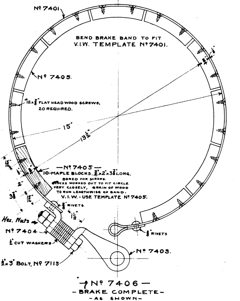
Part of that was a band brake, which is shown below.
Band or belt brakes were more commonly used in the past than now, but it’s still considered an important part of engineering education, especially in statics. A summary of the theory behind it is below, from Targ’s Theoretical Mechanics:


In American usage the formula is usually written in this way:
P = Q eμα (1)
where
- P = Force applied on one end of the belt, tangential
- Q = resisting force on the other end of the belt
- α = angle of wrap around the drum (as shown above, the belt can be wrapped more than once if properly configured)
- μ = coefficient of friction
The torque on the drum (the I.D. of the brake shown above) can be computed in this way, taking moments around the centre of rotation:
T = (P – Q)*r (2)
where r is the radius of the drum.
Turning to the brake shown above, it’s a fancier construction than many, with an outer steel band and a series of wood brake shoes screwed into the steel band. Let us assume that μ = 0.49. As far as the angle is concerned, a little inspection will reveal that there are ten (10) blocks and that, if the circle were closed, there would be twelve blocks, thus α = (10/12)(360) = 300 degrees = 5.24 radians (which are necessary for Equation (2)). Inserting these values into Equation (1) shows that
P = 13 Q (1a)
In reality we apply the force P, so the formulation in Targ makes more sense. Let us apply a force of P = 500 lb. then Q = 500/13 = 38.44 lbs. The resisting torque (the radius is, from the drawing, (13 1/2)/2)*(500-38.44) or,
T = 3115.56 in-lbs. (2a)

