
We’ve been posting some pretty technical stuff lately. While there is a good deal of that here, we’re going to use this to illustrate two things: how projectile motion works and why you shouldn’t put starter fluid in a diesel hammer.
The Situation
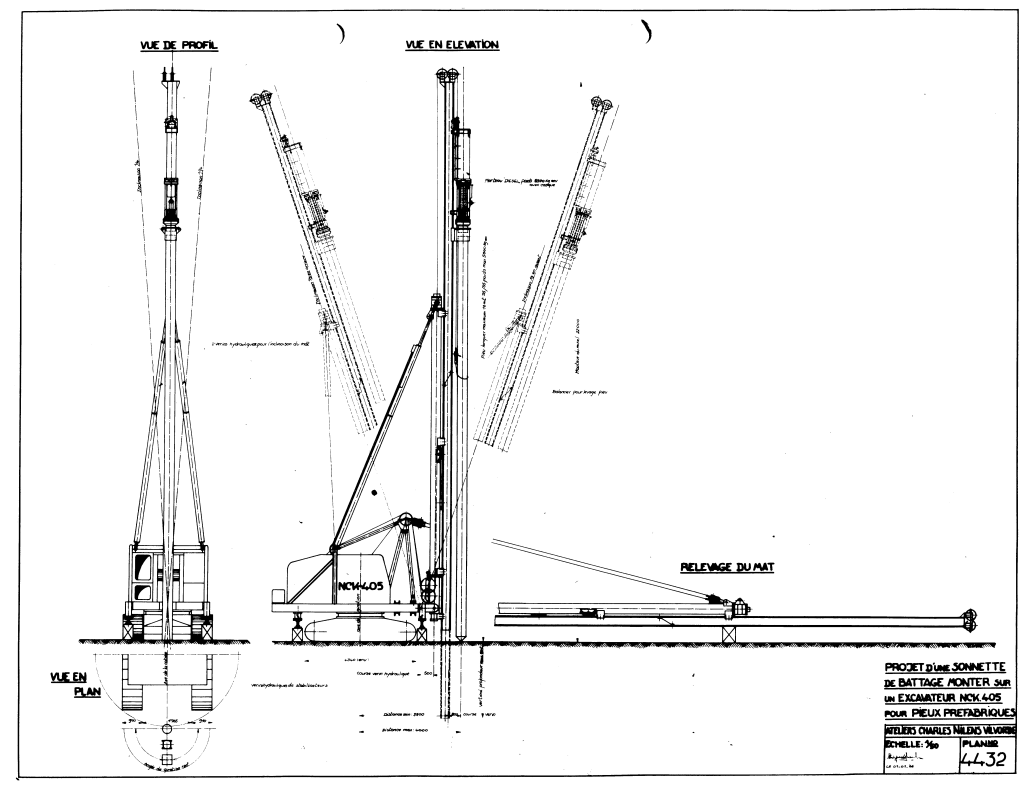
Let’s consider the situation where the contractor brought the rig illustrated below (for which he was the sole bidder) to the jobsite.

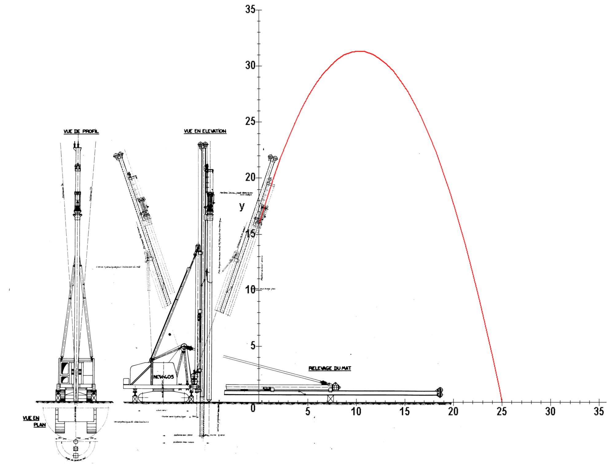
The hammer is in 1:3 in batter (that’s explained in the image to the right.) This translates into a 18.43 degree angle from the vertical, or a 71.57 degree angle from the horizontal (the importance of that will become evident shortly.) This means that the phantom view above leaning to the right is the starting point of the hammer; the combustion chamber is 15.85 m above the ground surface. The ground surface is level.
Having turned down the services of a reputable pile hammer repair organisation, the contractor has a lot of trouble with the rig, from the cab up. Once he gets the rigging in place, the hammer has trouble starting. Frustrated, the job superintendent orders a carpenter to go up the mast with starter fluid and “get this *!#%@ hammer running!” The carpenter dutifully goes up the mast (which is a more dangerous operation that doing it in American U-style leaders, although with a mast it’s not hard to lower the entire assembly) and signals the crane operator to lift the ram with the starting device (or crab) enough to open the exhaust ports. He empties the entire can into the combustion chamber and hurries down the best he can. When he clears the rig the crane operator continues to lift the ram until the starting device releases the ram and it comes down. The starting fluid and whatever diesel fuel is in the chamber detonates and the ram goes up…and up and up.
All five rings blow through the catch ring groove and the ram, separating from the cylinder and becoming airborne. This spectacular flight continues until it lands on the ground and buries itself 25 m down range from the start, right in front of the construction trailer. The occupants of that trailer are terrorised and exit out whatever opening they find on the back side of the trailer. The superintendent continues with a barrage of unprintable (well, on this site) language, but eventually manages to gather most of his crew and the occupants of the trailer together, calls a halt to the day’s work, and calls the reputable pile hammer repair organisation to see what can be done to get the hammer back together and working and fix the problems with the rig that had been plaguing him before that.
The Theory
Projectile motion is the combination of two things: the vertical and horizontal motion of the projectile. The vertical motion is basically the same described in How the Saximeter Works, and Why You Can’t Use It on a Vulcan (or any other External Combustion) Hammer. The horizontal motion lacks the gravity component; since we’re assuming no resistance due to air, the horizontal velocity is constant.
As explained in this post, the general vector form of the position of the ram at any time is

The equations for x(t) and y(t) (the components in the x- and y-direction respectively) are given by the equations


The initial velocity v0 is broken up into x and y components. The initial displacement (x0, y0) does not have to be at the origin, and for this example is not. The gravitational constant gc = 9.81 m/sec2; since the only force on the ram is its weight, the mass of the ram is not required.
The components of the initial velocity are as follows:


The angle θ is the angle of the hammer’s inclination relative to the horizontal axis (in this case the ground.) This is customary for projectile motion calculations but is contrary to pile driving practice, which focuses on the angle relative to the vertical (plumb) axis.) When the substitutions are made, the position vector is as follows:

The x-displacement is the part which multiplies by the i vector; the y-displacement is the part which multiplies by the j vector.
We note that both displacements are functions of time; one thing we’d like to do is to determine the x-y displacement curve of the ram. Usually you have to solve both displacements for time, equate them and solve for y, but in this case it’s easier to solve the x-displacement for time (since it’s linear) and substitute it into the y-displacement. Solving the i term of Equation (4) for time yields

Substituting this into y(t), we have

The down range point at which the ram makes impact can be found by substituting y(t) = 0 and x(t) = ximpact into Equation (6) and solving,

The Example Solved
For this problem we need to determine the following (other things can be obtained from this theory as well):
- Maximum height of the flight of the ram; and
- Initial velocity of the ram.
At this point the known variables are as follows:
- ximpact = 25 m
- gc = 9.81 m/sec2
- θ = 71.57 degrees
- x0 = 0
- y0 = 15.85 m
Substituting these into Equation (7) will yield v0 as the only variable left. There are a number of ways to solve this, but the solution for this is v0 = 18.37 m/sec. By comparison, the rated impact/combustion chamber exit velocity of a 3 m stroke diesel hammer is 7.67 m/sec.
As far as the maximum height of the ram’s flight, we take the derivative of Equation (6) and set the left hand side to zero and solve for the x-coordinate at which the elevation of the ram is at its maximum. This brings us

Substituting the variables above yields xymax = 10.32 m, and substituting that for x(t) in Equation (6) shows that ymax = 31.33 m, and substituting this value of x into Equation (5) shows us that this took place 562 msec into the flight.
An illustration of the ram’s flight path is at the top of the post; it’s reproduced below, with the x and y axes superimposed as well.

Tangential and Normal Components of Acceleration
As a further exploration, we should consider the tangential and normal components of acceleration. The discussion here is based on Theoretical Mechanics – A Short Course -Targ. An illustration of the problem from that text is below.
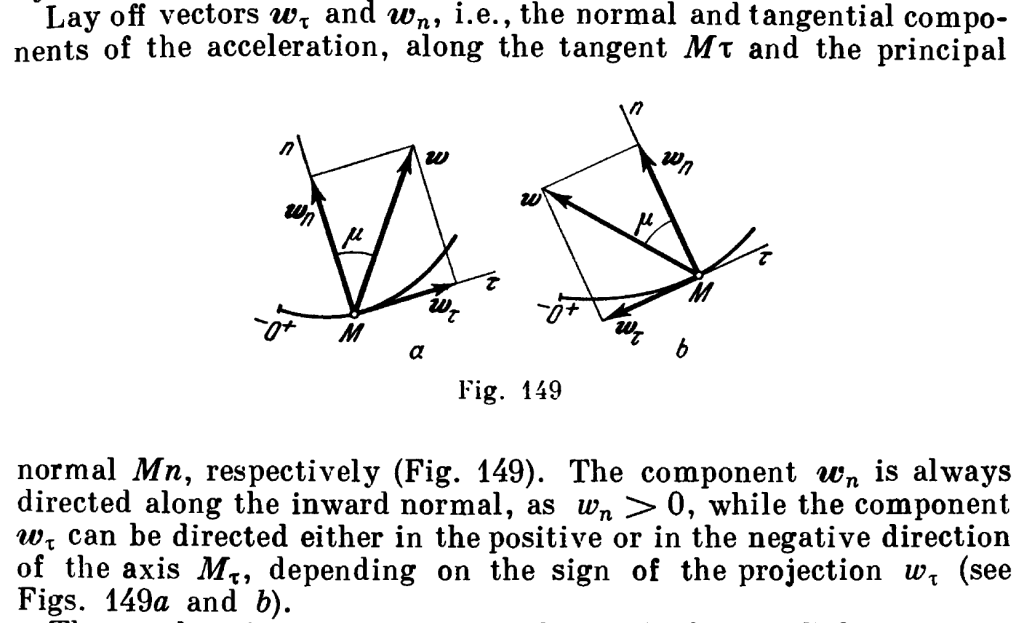
From this and other considerations we can make the following observations about normal and tangential acceleration as follows:
- All velocity is tangential, i.e., in the direction of motion.
- The tangential acceleration is the acceleration in the direction of motion, the same as velocity.
- The normal acceleration is in the direction of curvature and perpendicular to the tangential acceleration, of the magnitude
, where
is the radius of curvature and v is the scalar value of the velocity
- For straight line motion, all acceleration is tangential.
- For purely curved motion (i.e.
constant,) all acceleration is normal.
- For motion where the radius of curvature varies as a finite number, it is a combination of both.
With this in hand, we need to start with Equations (4) and (5). The two derivatives of the former are as follows:

and

Note that Equation (10) shows that the only acceleration is the downward acceleration of gravity, as we would expect.
The scalar velocity, from Equation (9), is

and the tangential acceleration is the derivative of that scalar velocity, thus

Now we consider the function of the flight path independent of time, which is given in Equation (6). To compute the radius of curvature, necessary for the normal acceleration, we need the two derivatives of that equation, which are

and

The radius of curvature at any point (from calculus) is thus

Based on the formula in the observations above, the normal acceleration is

These formulas look complicated, and are; however, most of the variables are constants either given earlier or computed earlier (like the initial velocity.) So we will present the results in substituted form. We will give the results in two ways: as a function of x and at the point x = 15 m. The results (with some comments) are as follows:

We can clearly see the parabolic nature of the flight path.


4 thoughts on “Projectile Motion, or Why You Don’t Put Starter Fluid in a Diesel Hammer”