
In the post Checking the Soviets: Determining the Eccentric Moment, we discussed the process of determining this parameter and more for a vibratory eccentric. The importance of the pendulum frequency–and the way that rotational moment of inertia and mass moment of inertia can easily be related with this kind of configuration–was discussed in Two Papers on Vibratory and Impact-Vibration Hammers. In this post we will “dig down” more deeply into just how the eccentric moment and rotational inertia are computed.
Basic Objectives and Assumptions
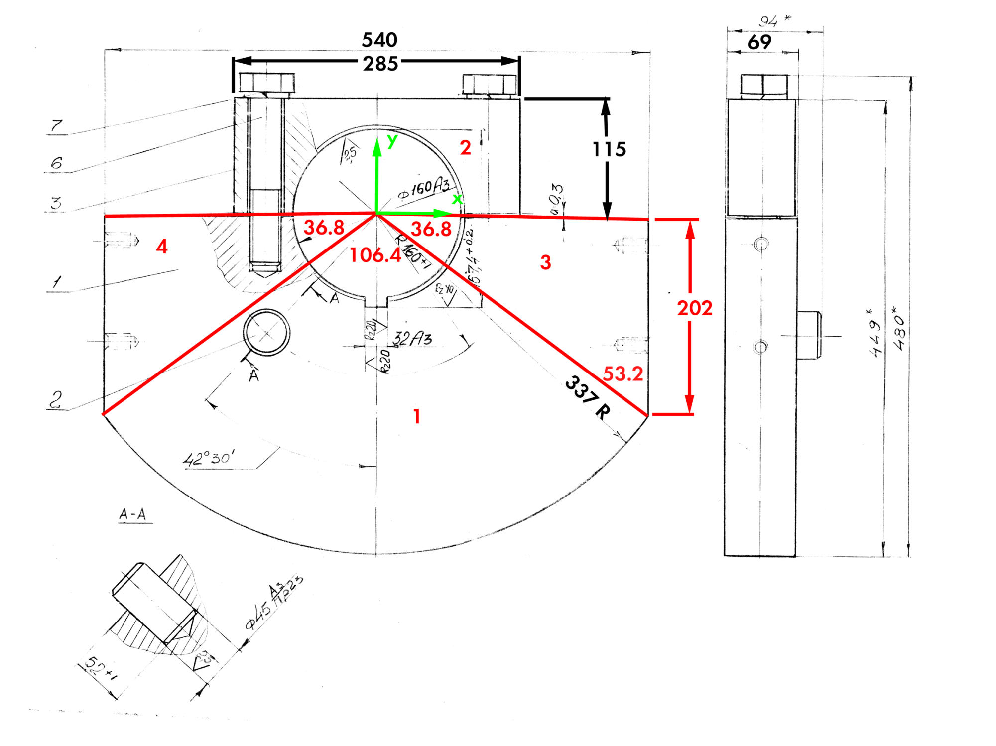
The drawing for the eccentric assembly (and it is an assembly) is shown above. It is an eccentric for the Soviet VI-722 vibratory driver, a machine where, using a gearbox, the frequency and eccentric moment could be changed. It’s a little different than what we see in American machines in that, instead of the eccentric being one piece, a bolt-on piece (3) is added to secure the eccentric (1) to the shaft. The calculations will be done manually, i.e., the assembly will be broken up into pieces and analysed in that way.
Because the drawing isn’t the best quality, I’ve added some dimensions in black to make sure they’re legible. (All dimensions are in millimetres.) The lines and regions marked in red are the divisions I have made for the analysis. There is more than one way to divide this piece up; this one was chosen because all of the regions border/touch the origin. Since the rotational moment of inertia J0 is taken from the centre of the coordinate system, this allows us to avoid using the parallel axis theorem. The green items mark the coordinate system.
The basic objectives are as follows:
- Determine the mass of each piece by determining the area, thickness and density of each piece.
- Determine the centres of gravity for each piece relative to the x- and y-axes.
- Determine the rotational inertia for each piece and sum them up for the assembly.
- Determine the mass moment of inertia of the system.
- Determine the eccentric moment of the system by determining the overall mass (adding all of them up) and centre of gravity of the system relative to the centre axis (weighted average.)
- Determining the pendulum frequency of the eccentrics.
In doing these we make the following assumptions.
- We will ignore the effects of the centres of gravity in the x direction except where they impact the rotational inertia. We do this because of symmetry.
- We will assume the shaft and keyway at the centre of the assembly are solid. IRL that’s the case.
- We will ignore the effect of the “saw cut” where the eccentrics, two of which are made in one piece, are separated. (This was a familiar problem with Vulcan manufacturing.) We will also ignore the effect of the bolt heads and assume the bolts make the retaining bracket (3) essentially solid.
- We will ignore the effect of the dowel pin in Section A-A, assume it’s a part of the solid plate.
- We will assume that we have a constant thickness of 69 mm, even though the bracket (3) is a little thinner than that.
- We assume that all of the parts are steel (which they are) and have a density of 7800 kg/m3.
- We will not make an attempt to separate the “eccentric” and “non-eccentric” portions of the assembly. Although this is well attested in the vibratory literature and design practice, it is not necessary for an accurate result, as explained in Checking the Soviets: Determining the Eccentric Moment.
Region 1: Circle Sector
Let us begin by noting that the rotational moment of inertia J0 is computed by the integral

Customarily the angle 

The area is

The centre of gravity is computed by the integral

Performing the integration,

The volume is

and the mass is

The variables for this region are as follows:
(this is the same for all of the sections)
(this is also the same for all of the sections)


Regions 3 and 4: Triangular Regions
For the remainder of the regions, we can use more “conventional formulae.” The tricky part is that, for these formulae, the base and the height changes depending upon the orientation of the triangles. For convenience, we will consider “b” as the side of the triangle along the x-axis and “h” as the side which cuts off the circular arc. We can thus use the formula for the the moment of inertia around an axis along a triangle side for 

That being the case,

and

The rotational inertia is the sum of the two, or

The area is

The centre of gravity in the y-direction is

The volume is

and the mass is

Obviously the effect of this has to be doubled. The variables for this are as follows:


Region 2: Rectangle
This is similar to the triangles in that, for the two different directions, we have to switch the b and h. For the rectangle “b” is along the x-axis and “h” is in the y-direction.
For the moment of inertia around the x-axis with the base along the x-axis, the moment of inertia is

and around the y-axis (which runs through the centroid of the rectangle,)

Adding the two as in Equation (10),

The centre of gravity in the y-direction is along the y-axis and is

For the area, volume and mass, the quantities in Equations (11), (13) and (14) can be doubled.
The variables are as follows:


Adding Up The Results
Making all of the substitutions, the results can be summarised as follows:
| Region | J0, m4 | Area, m2 | CGy, m | Mass of Region, kg | Eccentric Moment  , kg-m , kg-m |
| 1 | 0.005988 | 0.10545 | -0.1937 | 56.8 | 11.00 |
| 2 | 0.000366 | 0.03278 | 0.0575 | 17.6 | -1.01 |
| 3 | 0.001179 | 0.02727 | -0.0673 | 14.7 | 0.99 |
| 4 | 0.001179 | 0.02727 | -0.0673 | 14.7 | 0.99 |
| Total | 0.008713 | 0.19277 | -0.1153 | 103.7 | 11.96 |
The values for CG are negative if they are below the x-axis, which most are. The eccentric moments, however, were the region mass times the negative of the CG to make the entire eccentric moment come out positive. The total value of J0 the area, mass and eccentric moment are simply the sum of the regional ones. The total value of the CG is simply the eccentric moment divided by the mass.
Based on considerations in the Two Papers on Vibratory and Impact-Vibration Hammers, the mass moment of inertia is computed by the equation

Determining the Pendulum Frequency
The pendulum frequency is determined by the equation

where 

Making the substitutions,

This is on the low side for vibratory hammers. More information on this topic can be found in the Two Papers on Vibratory and Impact-Vibration Hammers.


3 thoughts on “Determining the Eccentric Moment, Rotational Inertia and Pendulum Frequency for a Vibratory Eccentric”