
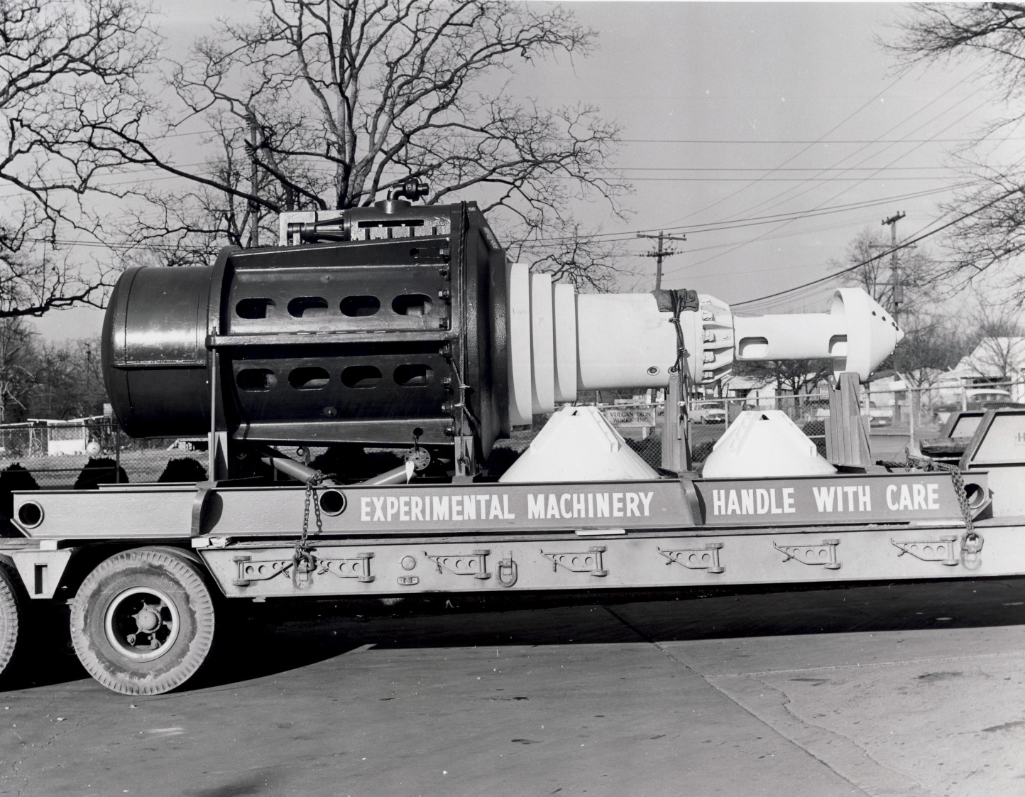
A common problem in elementary statics is picking up a load with a sling. It’s an important one in heavy lifting, and Vulcan certainly experienced a great deal of that. We’re going to look at an example: the Internal Pile Hammer IPH-16. It’s shown with its skid on the truck above; we’re going to look at how it got there, and do so in a different way from, say, this problem, where we used straight-up vector statics.
The Problem
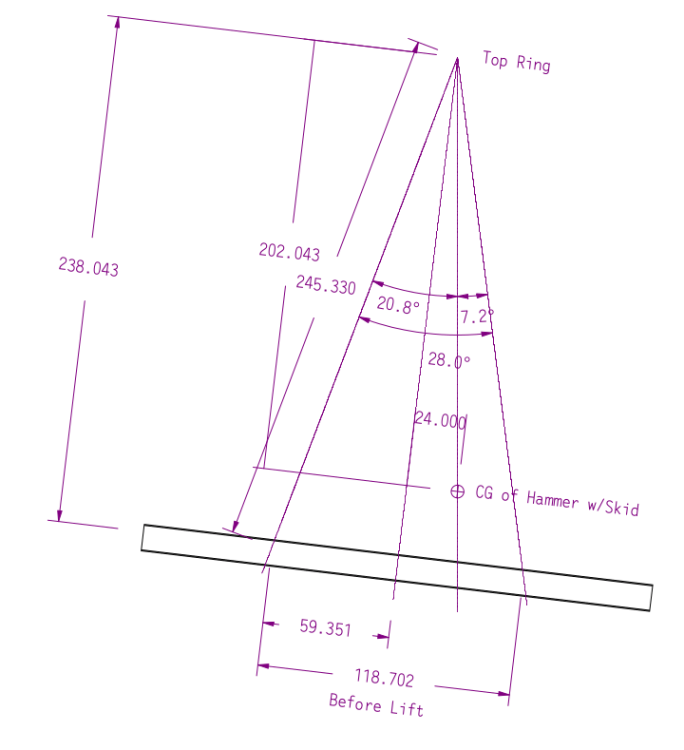
Vulcan’s drawing of the hammer and sling setup is shown below.
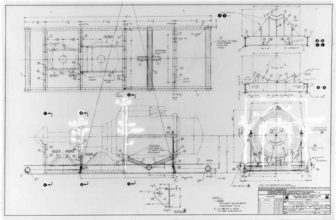
This arrangement was adapted from one Vulcan used on the 040 hammer. We’re going to analyse it without those cones on the skid you see on the left. Vulcan estimated the shipping weight of the hammer to be 48,000 lbs.
Solution Strategy
The cables shown in the drawing are inextensible, i.e., they can only be in tension. (Or, as a prof from Texas A&M used to say, you can’t push a block with a rope.) Like this problem, it’s technically a three-dimensional problem, but let’s look at a force diagram to see if a different approach might be justified.
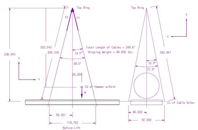
The centre of gravity (CG) of the hammer and skid is in the x-y plane, i.e., it is in the middle of the end view on the right. By symmetry we can assume that the loads on each set of cables is split evenly between the front cables and the back ones. Because of this we can turn this into a two-stage two-dimensional problem:
- We analyse the result in the x-y plane (left view) and determine the load split between the load on the right slings (F1) and the left slings (F2).
- We then take that result and analyse the load split between the front and back slings (y-z plane.)
We will do this graphically using the Parallelogram and Triangle Laws as shown below (this and the next diagram from Targ (1988).
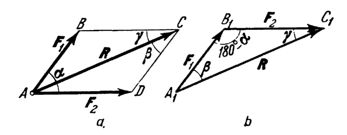
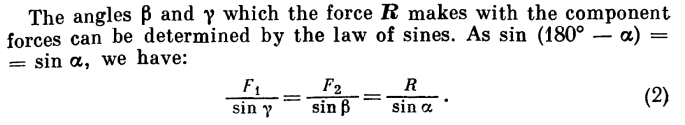
We can then check our graphical analysis using the Law of Sines:
With all that, if we look at the force diagram we constructed, all we need to is to sum the forces around the top ring, determine F1 and F2, and we’re done, right?
Wrong.
The problem is that, if we sum moments around the top ring, the offset CG produces a moment with no reaction to keep things in static equilibrium. The only thing we can do is to make it so that the weight W is directly below the top ring and the moment goes to zero. That’s what happens when you pick up a load with an off-centre CG, the load tilts until the moment goes away, which is what you can see below.
With that as our new force diagram (the one in the y-z plane is unchanged for our purposes) it is clear that the load is redistributed between the left and right slings, as we will see below.
Solving the Problem
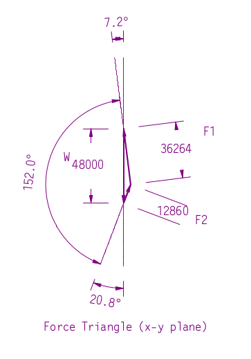
Since this is supposed to be a graphical solution, we’ll present the force triangle in the “tilted” x-y plane at the right. This represents the force summation at the top ring.
The Weight W is now acting vertically along the new y-axis. The side for F2 is parallel with the new orientation of the left sling, and F1 with the new orientation of the right sling. Getting these lined up is the “tricky” part of a problem like this. Once it’s done, however, the sides can be measured in CAD with a fair degree of precision.
So can we demonstrate this analytically? Using the law of sines,

For F1,

and F2,

The difference lies in the rounding of the angles. Skewing the load to one side is a significant problem in heavy lifting. Not only does a great deal of the load shift to one set of slings, but the load swings, which can be very hazardous. It’s possible that those conical pieces you see on the left were added, among other things, to balance the load.
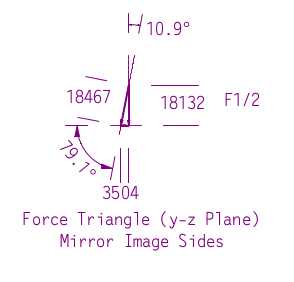
Now we turn to splitting the load between the two front and back slings of the right sling, which is the greater of the two. Since that load was assumed to be vertical, we also need to consider that the front and back slings are not in the x-y plane, and that too will add to the load. The diagram at the left shows half the load on each sling. The triangles remain even though the plane formed by the front and back slings is not parallel to any of the Cartesian planes.
As seen, the load on the slings is slightly higher than the vertical load, which is due to the tall nature of the rigging. The load in the z-axis is offset by an opposite load in the mirror image sling. It remains as an exercise to show that this result conforms with the Law of Sines as the previous one did.
Some Concluding Thoughts
In this problem we took a purely vector approach. This is more of an “old coot statics” approach. It can be very useful in situations where the problem is truly two-dimensional or the symmetry allows us to make it that way. If this was analysed at all, it was probably done in this way, complete with a hand-drawn graphical solution.


2 thoughts on “An Example of Balancing a Sling Picked-Up Load: the IPH-16”