

One thing that I bring up over and over again in my Soil Mechanics and Foundations courses is “static equilibrium,” the summation of forces and moments for a given foundation. That’s a good thing, because civil engineers are deeply disturbed when what they design moves and generally freak out when that happens. However, the usual introduction (really a baptism of fire) engineering students have to statics comes with Vector Statics. While vector statics have been around a long time and are very versatile at determining loads and moments, they emphasise a formulaic approach to the problem and not one where the engineer gets a “feel” for what’s going on. That’s especially true in geotechnical problems (principally shallow foundations) where the complexities of applying vector statics aren’t justified by the problem.
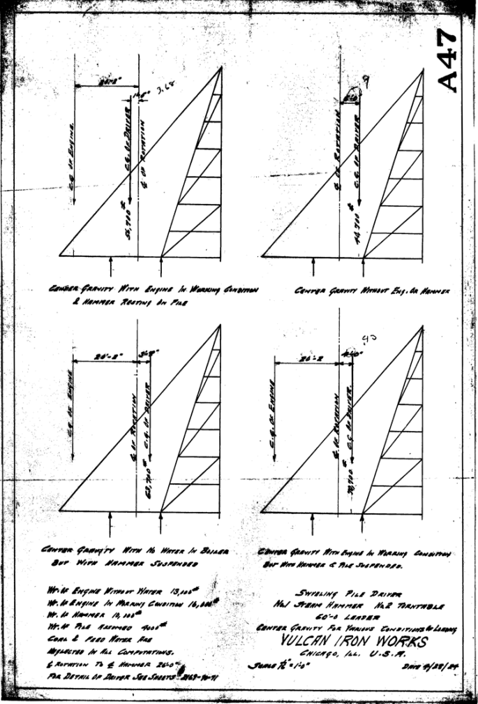
As a simple (and not very geotechnical) example, consider the two-ton stiff leg derrick shown below. It dates from 5 July 1898.

Although the drawing gives away the load the derrick picks up as two U.S. tons, for the moment we’ll just assume the load picked up has a weight of W. Also note that we’ve rotated the coordinate system so that y is downward positive and x is leftward positive. We still have a right-handed coordinate system but one which is more congenial to geotechnical sensibilities. We assume the weight picked up as positive downward W but the two reactions F1 and F2 are assumed to be negative upward.
Let’s start with the vector statics approach. The weight is simply expressed by 

The moment is given by the cross product of the force and the moment arm, computed using the familiar determinant of the following:

Substituting yields

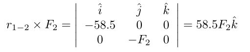
In like manner, the force at point 2 is -F2, and the moment arm is

and the cross product of F2 with r1-2 is
Summing the moments yields

and solving for F2, we have at last

What this tells us is that, since W is positive, the direction of F2 is opposite of what we assumed. Basically with a stiff leg derrick like this the whole structure pivots around point 1.
If we did this “according to Hoyle” we would probably have done the summation of forces first. Better late than never:

Substituting our result for F2 yields

and solving for F1

Our assumption regarding the direction of F1 was correct. It’s also possible to assume all the forces to be positive but the result will be the same.
Now let’s turn to the “old coot” method, where we dispense with the vector formalities and solve the problem in a more direct fashion. It works in cases like this for two reasons:
- In a two-dimensional case, all of the moments are “out of the paper,” i.e., in the
or z direction. Thus they can be summed without worrying about the direction of the moment.
- For moments, the moment arm component which is parallel to the direction of the force is irrelevant. You can see this for yourself if you work your way through the math. Only the moment arm distance which is perpendicular to the force is important. For problems like this where all of the forces are in the direction of one of the two axes, this is a simplification. The “old coot” method can be used if this is not the case but it’s a little more complicated.
Let’s take moments around point 2 this time. The moment of the weight around point 2 is the horizontal distance between the two times the force, or

Note with the old coot method we have to pay attention to the rotation of the moment. Counterclockwise (anticlockwise) moments are positive. For the moment due to F1,

which is obviously clockwise. Summing these moments,

which solves to
This is the same as before. The summation of forces is

which again is the same as before without the unit vectors. As before F2 solves to
The old coot method can be used to solve for a wide variety of engineering problems, provided the people who use it really know what they’re doing. In the case of lifting structures like this, it’s safe to say that virtually all cranes (including those which lifted the leaders for Vulcan hammers) are designed from the same principle as we see in the stiff leg above. Some observations are as follows:
- The forces F1 and F2 assume point loads at these locations, or where the structure is fixed to the ground/foundation. This is a reasonable assumption.
- The location of the weight W depends upon how far out the block and tackle let the boom down. If the boom is vertical (which is practically prevented by the stiffening wires) then W = F1 and F2 = 0.
- For a stiff leg like this, the foundation at F2 must be made to withstand the tension load there. For most mobile cranes and excavators, they use counterweights to…well, counter the upward force of F2. Adequate counterweight is crucial for the success of a mobile crane or excavator. If the counterweight is inadequate (or put mathematically Wcounter < F2) then the lifting device will turn over and you will have a serious accident. This is true irrespective of how well you have designed the structure of the crane or excavator. One common counterweight with crane-mounted leaders for Vulcan hammers was the boiler or air compressor (prime mover) itself.
- The above analysis does not consider the weight of the stiff leg itself, which certainly affects its performance.


6 thoughts on “Vector Statics and “Old Coot” Statics: An Example”